This article explores various diode-based clipper circuits, including series, shunt, and biased clipper circuits, emphasizing their functional roles in shaping and adjusting waveforms.
P-N junction diodes are primarily used in power supplies to rectify AC to DC voltages. However, it is by no means the only application of diodes. In fact, there are many other common applications, such as clipping, clamping, and multiplying voltages. In this article, the clipper circuits and their types are discussed in detail.
What is a Clipper Circuit?
The clipper circuit, also known as a limiter circuit, is a diode circuit that is used to eliminate a portion of a waveform.
The basic operating principle of a clipper circuit is similar to a half-wave rectifier since a clipper eliminates one of the alternations of an AC input signal at the output of the circuit. There are four types of clipper circuits, as shown in Figure 1, which are negative series clipper, positive series clipper, negative shunt clipper, and positive shunt clipper.
Types of Clipper Circuits
Series Clipper Circuits
Each series clipper contains a diode that is in series with the load, while each shunt clipper contains a diode that is in parallel with the load.
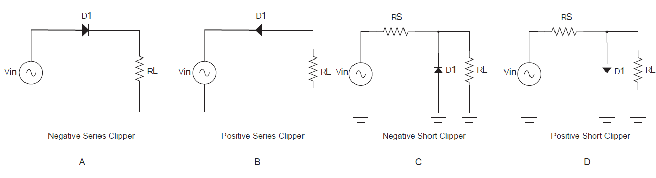
Figure 1. Series and shunt clipper circuit diagrams
Note, in Figure 2(a), that when the diode in a negative series clipper is forward biased by the input signal, it will conduct, and a voltage will appear across $R_{L}$. When the diode in the negative series clipper is reverse-biased by the input signal, it does not conduct. Therefore, no voltage will appear across the load resistor.
A positive series clipper and its associated waveforms are shown in Figure 2(b). The positive series clipper operates in a similar manner. Note that, compared to series clippers, the output voltage polarities are reversed. Also, the current directions through the circuit are reversed.
Clippers are used for various functions, including altering waveforms, providing circuit transient protection (reducing voltage spikes), and as amplitude-modulated (AM) communications receiver detection circuits.
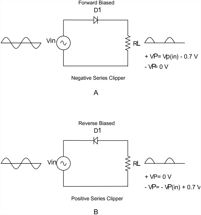
Figure 2. Input and output waveforms for series clippers. (a) Negative series clipper. (b) Positive series clipper.
Shunt Clippers
The operation of the shunt clipper is exactly opposite to that of the series clipper. The series clipper provides an output when the diode is forward-biased and no output when the diode is reverse-biased. The shunt clipper provides an output when the diode is reverse-biased and shorts the output signal to ground when the diode is forward-biased. This operation is illustrated in Figure 3.
The circuit shown in Figure 3(a) is a negative shunt clipper. When the diode in the negative shunt clipper is reverse-biased, it is effectively removed from the circuit. With the diode reverse-biased, the resistors form a voltage divider, and the load voltage can be found by the formula shown in Figure 3(a). The output signal is similar to the positive alternation of the input. The peak output voltage is slightly less than the peak input voltage. The output of the circuit is approximately 0.7 V when the diode is forward biased.
The positive shunt clipper, shown in Figure 3(b), is similar in operation to the negative shunt clipper. When the input to the circuit is negative, the diode is reverse-biased and, for all practical purposes, removed from the circuit. Note that $R_{S}$ is added in the shunt clipper as a current-limiting resistor. If the input signal forward biased the diode and $R_{S}$ was not in the circuit, $D_{1}$ would short the source. The signal would be shorted to ground during the positive alternation of the input signal. This could result in the diode being destroyed by excessive forward current. Also, the signal source could be damaged by the excessive current demand of the conducting diode. The value of $R_{S}$ is much lower than the value of the load resistor ($R_{L}$). When the diode is reverse-biased, the voltage across the load resistor is approximately equal to the value of $V_{in}$.
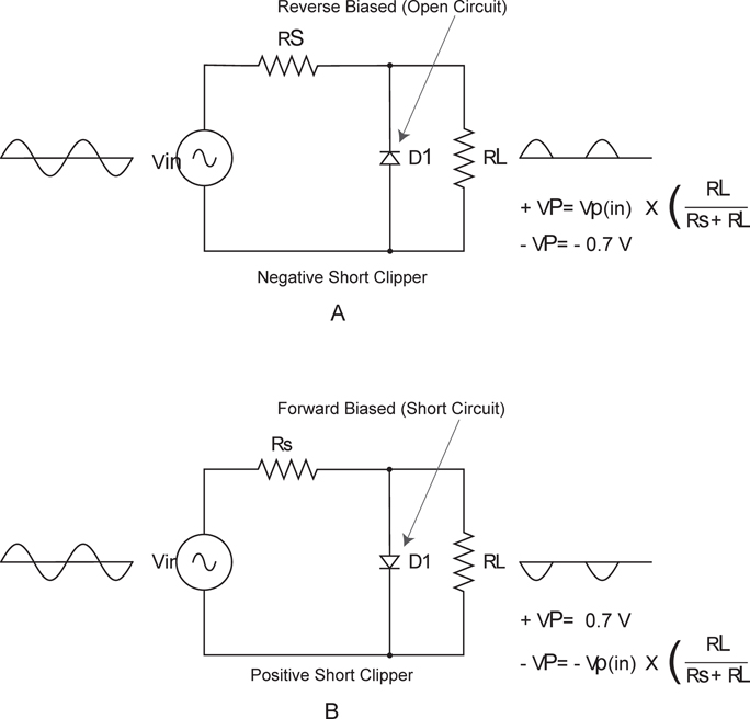
Figure 3. Input and output waveforms for shunt clippers. (a) Negative shunt clipper. (b) Positive shunt clipper.
Biased Clippers
Biased clippers have a DC bias source to set the limit of the output voltage of the circuit. Figure 4 shows positive-biased and negative-biased clipper circuits. These circuits are designed to clip input waveforms at values other than the diode $V_{F}$ (0.7 V). In both circuits, the bias voltage ($V_{B}$) is in series with the shunt diode. The diode conducts and clips the input waveform as shown. A positive-biased clipper (see Figure 4(a)) is designed to clip the input signal at $V_{B} + 0.7, \text{V}$. The bias voltage determines the value at which the input signal is clipped. The negative-biased clipper of Figure 4(b) is similar.
A variable DC source could be used to provide an adjustable value of $V_{B}$. The bias voltage ($V_{B}$) would allow an adjustment in this circuit to provide the desired clipping limit. By reversing the direction of the diode and the polarity of the variable DC voltage in both circuits of Figure 4, the circuit would function as a negative-biased clipper.
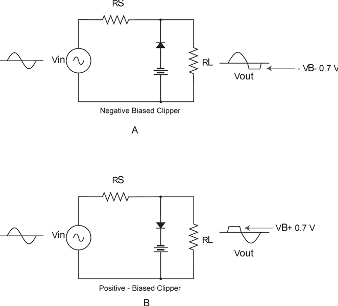
Figure 4. Biased clipper circuits. (a) Positive-biased clipper. (b) Negative-biased clipper.
Review Questions
Answer the following questions.
- A clipper is used to __________ .
- Another name for a clipper is __________ .
- The difference between a series and shunt clipper is __________ .
- The purpose of $R_{S}$ in a shunt clipper is __________ .
- A biased clipper uses a __________ to establish a reference voltage.
Answers
- eliminate a portion of a waveform
- limiter
- the diode placement (series or parallel with the load)
- to limit the current through the diode
- DC bias source
Key Takeaways
Clippers and their variations, including shunt, biased, and series types, play a critical role in waveform shaping, signal conditioning, and transient suppression. Their importance is evident in communication systems, protective circuits, and power regulation, making them fundamental tools in both analog and digital electronics.