This article explains transformer coupling in amplifiers, focusing on its operation, impedance matching, circuit design, advantages, and limitations.
Transformer coupling stands out as a unique coupling method in amplifier systems, as it utilizes mutual inductance and allows for effective impedance matching and DC isolation while transferring AC signals between stages. Its practical application in radio receivers and audio output stages highlights its significance, especially in frequency-selective circuits.
Principles of Transformer Coupling
In transformer coupling, the output of one amplifier is connected to the input of the next amplifier by mutual inductance. Depending on the frequency being amplified, a coupling transformer may use a metal core or an air core. The output of one stage is connected to the primary winding, and the input of the next stage is connected to the secondary winding. The number of primary and secondary turns determines the impedance ratio of the respective windings. The input and output impedance of an amplifier stage can be easily matched with a transformer. AC signals easily pass through the transformer windings. DC voltages are isolated by the two windings.
Figure 1 shows a two-stage transformer-coupled radio frequency (RF) amplifier. This particular circuit is used in an amplitude-modulated (AM) radio receiver. Circuits of this type are generally built on compact printed circuit boards (PCBs). The operational frequency of this amplifier is in the kHz to MHz range.
The operation of a transformer-coupled circuit is very similar to that of a capacitive-coupled amplifier. Biasing for each transistor element is achieved by resistance and transformer impedance. The primary impedance of $T_{2}$ serves as the load resistor of $Q_{1}$. The secondary winding of the transformer and $R_{4}$ serve as the input impedance for $Q_{2}$. The low output impedance of $Q_{1}$ is matched to the high input impedance of $Q_{2}$ by the transformer. The primary tap connection is used to assure proper load impedance of $Q_{1}$.
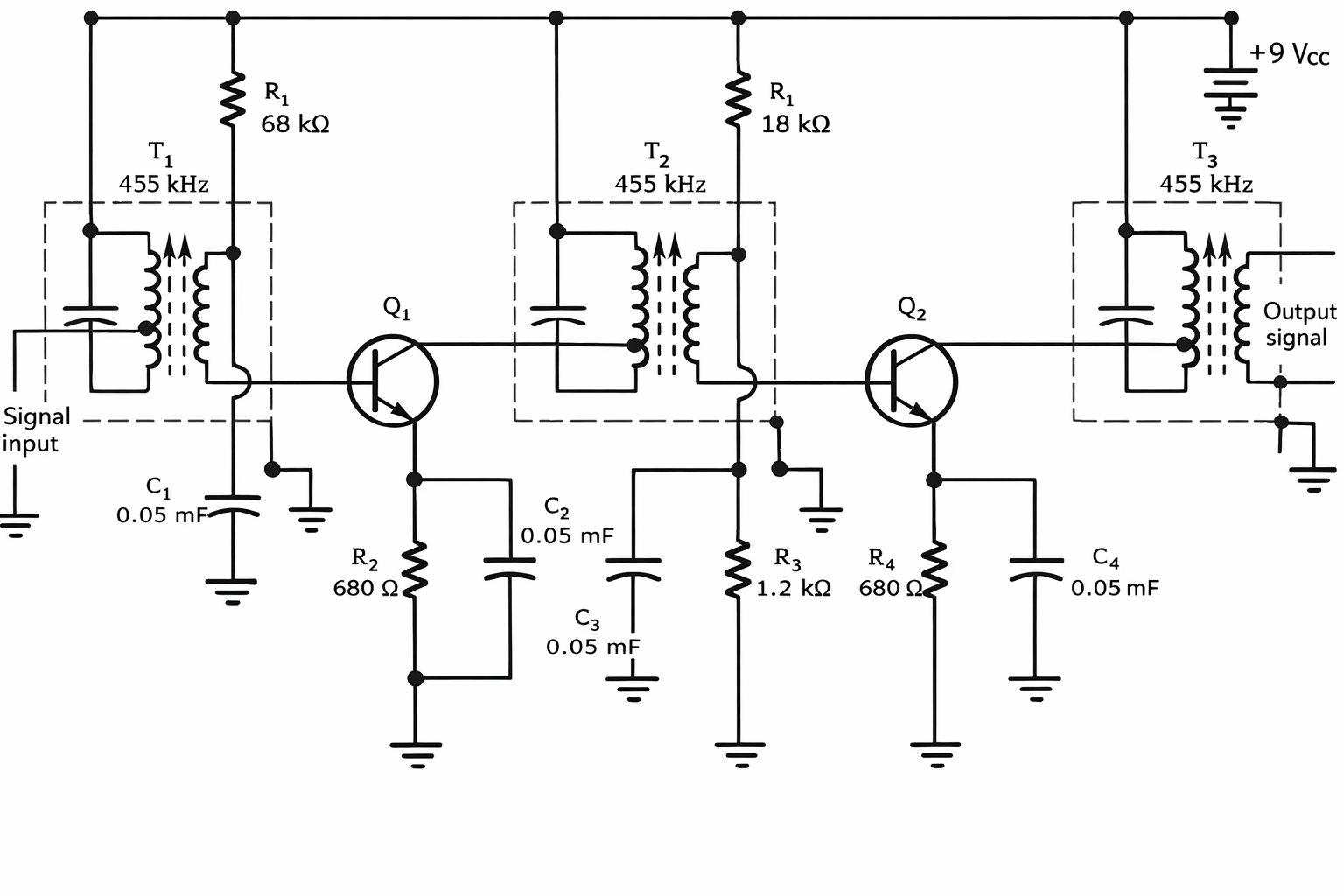
Figure 1. Two-stage transformer-coupled RF amplifier circuit design
This particular transformer-coupled amplifier is tuned to pass a specific frequency. The selection of this frequency is achieved by coil inductance ($L$) and capacitance ($C$). Tuned transformer-coupled amplifiers are widely used in radio receivers and TV circuits. The dashed line surrounding each transformer indicates that it is housed in a metal can. This is done purposely to isolate the transformers from one another.
Transformer as an Output Coupling Device
Transformers are also used to couple an amplifier to a load device. Figure 2 shows a transistor circuit with a coupling transformer. In this application, the coupling device is called an output transformer. The primary transformer winding serves as a collector load for the transistor. The secondary winding couples the transistor output to the load device. The transformer serves as an impedance-matching device. Its primary impedance matches the collector load. In a common-emitter amplifier, typical load resistance values are in the range of 1000 $\Omega$. The output device in this application is a speaker. The speaker impedance is 10 $\Omega$. To get the maximum transfer of power from the transistor to the speaker, the impedances must match. The primary winding matches the transistor output impedance. The secondary winding matches the speaker impedance. Maximum power is transferred from the transistor to the speaker through the transformer impedance.
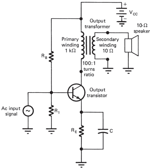
Figure 2. Transformer-coupled transistor circuit design
The number of turns of wire on a particular coil determines its impedance. Assume that the output transformer in Figure 2 has 1000 turns on the primary ($N_{pri}$) and 100 turns on the secondary ($N_{sec}$). Its turns ratio ($n$) is
$$n = \frac{N_{pri}}{N_{sec}} = \frac{1000}{10} = 100$$
The impedance ratio of a transformer is the square of its turns ratio, where $Z_{in}$ is the primary impedance and $Z_{out}$ is the secondary impedance. This is expressed as:
$$n^{2} = \frac{Z_{pri}}{Z_{sec}}$$
For the output transformer being considered in this example, the impedance ratio is $10^{2}$, or 100. This means the input or impedance of the transformer primary connected in the collector portion of the BJT circuit is 100 times more than the impedance of the load device. If the load (speaker) of this circuit has an impedance of 10 $\Omega$, the input impedance is $100 \times 10\Omega$, or 1 k$\Omega$.
Example 1
Calculate the input (primary) impedance of a transformer having a turns ratio of 25, which is connected to a load impedance of 4 $\Omega$ on the output (secondary) side.
Solution
$$n^{2} = \frac{Z_{pri}}{Z_{sec}}$$
$$25^{2} = \frac{Z_{pri}}{4}$$
$$625 \times 4 = Z_{pri}$$
$$Z_{pri} = 2500\Omega$$
Transformer coupling has a number of problems. In sound system applications, the impedance increases with frequency. As a result of this, the high-frequency response of a sound signal is rather poor. Better-quality sound systems do not use transformer coupling. The physical size of a transformer must also be quite large when high-power signals are amplified. Because of this, low-power and medium-power amplifying circuits only use transformer coupling. In addition to this, good-quality transformers are rather expensive. These disadvantages tend to limit the number of applications of transformer coupling.
Review Questions
- In transformer coupling, signal transfer between amplifier stages occurs through __________.
- Transformer coupling is ideal for __________ matching between amplifier stages.
- The frequency tuning in transformer-coupled amplifiers is achieved by adjusting __________ and __________.
- In the output transformer example, the turns ratio is defined as the ratio of __________ turns to __________ turns.
- The impedance ratio of a transformer is equal to the __________ of the turns ratio.
- The secondary winding of the transformer in a transistor output stage is connected to the __________.
- Transformer coupling is mostly avoided in high-fidelity audio systems due to poor __________ response.
- In a transformer with a turns ratio of 10, the impedance ratio is __________.
Answers
- mutual inductance
- impedance
- inductance, capacitance
- primary, secondary
- square
- load device
- high-frequency
- 100
Key Takeaways
Transformer coupling plays a critical role in amplifier design where impedance matching and signal isolation are essential, particularly in RF and medium-power applications. It allows for maximum power transfer between stages and between an amplifier and a load, such as a speaker. Despite limitations like size, cost, and limited high-frequency response, transformer coupling remains indispensable in many communication and signal-processing circuits.