The article discusses the working principle of Maximum Power Point Tracking (MPPT) charge controllers, highlighting how they optimize solar energy conversion by continuously tracking and adjusting to the maximum power point. It also explains the role of components like DC-DC converters and the Perturb and Observe algorithm used in achieving efficient energy transfer.
Maximum power point tracking (MPPT) charge controllers eliminate much of the energy loss found in the other types of controllers and produce efficiencies up to 30% over non-MPPT controllers. They are the most widely used type of charge controller, especially in larger systems.
How MPPT Works?
The MPPT tracks the voltage and current from the solar module to determine when the maximum power occurs in order to extract the maximum power. The MPPT then adjusts the voltage to the battery to optimize the charging. This results in a maximum power transfer from the solar module to the battery. MPPT charge controllers normally use PWM in their operation.
Maximum power point tracking (MPPT) is the process for tracking the voltage and current from a solar module to determine when the maximum power occurs in order to extract the maximum power.
In Figure 1, the blue curve is the current-voltage characteristic for a certain solar panel under a specified condition of incident light. The red curve is the power showing where the peak occurs, which is in the knee of the I-V curve (blue dot) at IMMP and VMMP. If the incident light decreases, the curves shift down.
The maximum power point tracking (MPPT) charge controller incorporates PWM and a DC to DC converter.
A simplified block diagram of the functional concept is shown in Figure 2. The Maximum power point tracking (MPPT) can be implemented in several ways, so the figure illustrates only the basic functions.
The purpose of the DC to DC converter is to isolate the DC input from the DC output so the output can be adjusted for maximum power. The MPPT control typically employs a microprocessor.
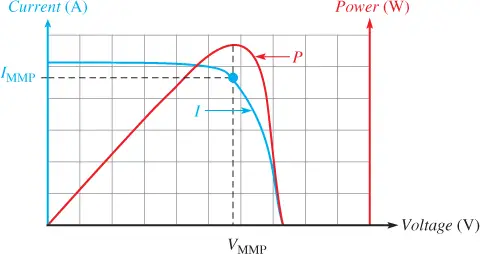
Figure 1 Solar Module I-V and Power Curves
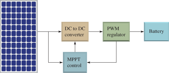
Figure 2 Maximum power point tracking (MPPT) Charge Controller Circuit Diagram
The output current of a solar module varies directly with the amount of light (irradiance) as shown in Figure 3a.
The maximum power that can be delivered will be greater at a higher irradiance, by reducing the load and maintaining the voltage at a constant level.
For changing temperature, the output voltage changes inversely, while the current remains relatively constant, as illustrated in Figure 3b.
Notice how the maximum power point (MMP) (blue dot) changes in both cases. The function of MPPT is to keep the operating point of the solar module at the maximum power point as the I-V curves change with changes in light or temperature.
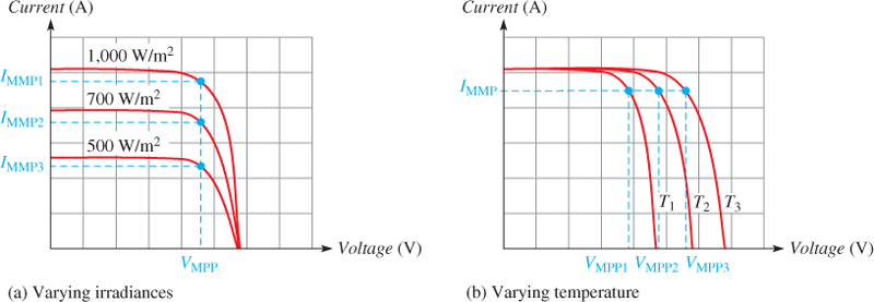
Figure 3a & 3b MMPs for Varying Irradiance and Temperature
Maximum power point tracking (MPPT) operates using an algorithm, which is basically a series of steps or procedures that is used to accomplish a desired result. Various algorithms are used in MPPT, but we will focus on just one called the Perturb and Observe Algorithm.
Perturb and Observe MPPT Algorithm
The Perturb and Observe (P&O) algorithm is a procedure in which a variable is changed (perturbed) and the effect of the change on another variable is monitored (observed). (P&O is also known as the hill-climbing method.)
The graphs in Figure 4 illustrate points along the I-V curve and the power curve that could be used in applying the P&O algorithm.
One method for moving the solar module output voltage along the I-V curve is to vary the load on the module incrementally until the maximum power point (MPP) is located. An I-V curve is shown in Figure 4a.
The Maximum power point tracking (MPPT) starts by setting a load value and measuring the module output voltage V1 and the current. The power (P1) at V1 is calculated.
Next, the load is increased and P2 is calculated for V2. P2 is compared with P1 and, because P2 is greater than (>) P1 we are still on the uphill side of the MPP on the power curve shown in Figure 4b.
The MPPT then moves the module output voltage to V3 and calculates P3. P3 is greater than P2, so we are still climbing the power curve toward the MPP.
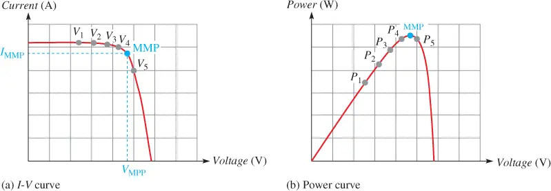
Figure 4a & 4b P&O Algorithm for Maximum power point tracking (MPPT)
The next measurement at V4 shows that P4 is greater than P3.
Finally, the measurement at V5 shows that P5 is equal to or less than (≤) P4, which indicates that the MPP has been passed and we are on the downhill side of the power curve. At this point, the MPPT reverses back to V4 and then goes back and forth (oscillates) between V4 and V5 on either side of the MPP.
The accuracy of this approach depends on the size of the voltage increments between each measurement. Smaller increments result in more accuracy and give a result closer to the actual MPP.
The flow chart in Figure 5 further illustrates the simplified P&O algorithm. Inverters come in many sizes and shapes. A typical Maximum power point tracking (MPPT) charge controller is shown in Figure 6.
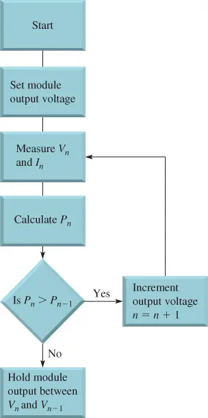
Figure 5 Perturb and Observe MPPT algorithm flowchart

Figure 6 Typical Maximum power point tracking (MPPT) Charge Controller.
Maximum Power Point Tracking (MPPT) Charge Controller Working
Figure 7 is a block diagram of an MPPT charge controller.
First, the MPPT microprocessor tracks and sets the solar module output at the maximum power point. The DC to DC converter consists of the DC to AC converter, the transformer, and the AC to DC converter.
The purpose of these blocks is to convert the VMPP to AC voltage and transformer-couple the AC voltage to the AC to DC converter, where the AC is converted back to a DC voltage.
As you know, a transformer is an electromagnetic device that works only with AC and isolates its input electrically from its output. The reason for the isolation is to allow the output DC voltage to be controlled independently of the voltage from the solar module.
The transformer can also step the AC voltage up or down, depending on what is required by the system.
The Maximum power point tracking (MPPT) microprocessor then adjusts the PWM switching regulator to produce the proper voltage required by the battery.
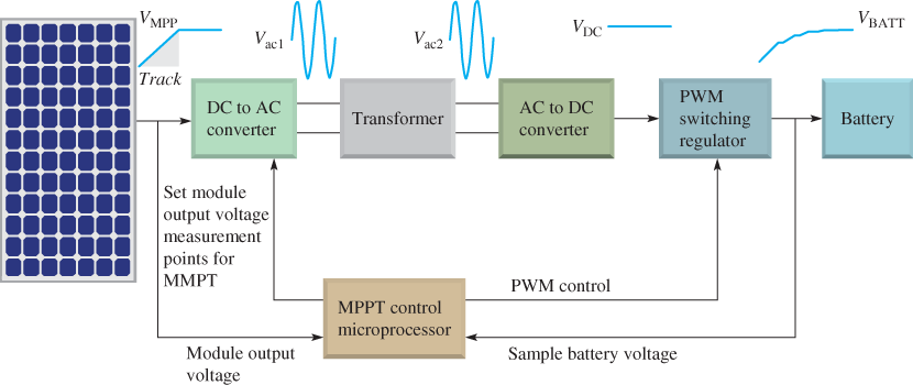
Figure 7 Operation of an MPPT Charge Controller
Maximum Power Point Tracking Review Questions
- What does MPPT stand for?
- What is the purpose of the dc to dc converter in the MPPT charge controller?
- What is Perturb and Observe?
- How does an MPPT know when the maximum power point has been reached?
- What is the hill-climbing algorithm?
Answers
- Maximum power point tracking
- It isolates the dc input from the dc output, so the output can be adjusted for maximum power.
- Perturb and observe; an algorithm that changes a parameter and observes the results
- The load is varied and the power is monitored to find the highest power.
- This is the same as the perturb and observe algorithm.
Maximum Power Point Tracking (MPPT) Key Takeaways
Maximum Power Point Tracking (MPPT) charge controllers play a critical role in maximizing the efficiency of solar power systems by continuously adjusting to the optimal voltage and current levels to extract the highest possible power from solar panels. Through the integration of DC-DC converters, microprocessors, and intelligent algorithms like Perturb and Observe, MPPT technology significantly reduces energy losses and adapts to varying environmental conditions such as irradiance and temperature. This makes MPPT controllers indispensable in solar energy applications, particularly in larger systems where energy optimization directly translates into improved performance, cost savings, and greater reliability for both residential and commercial installations.