The article provides an overview of inverter technology, explaining how inverters convert DC to AC power and detailing the different types of inverters—sine wave, square wave, and modified sine wave—along with their working principles and applications. It also covers the design considerations, waveforms, efficiencies, and suitability of various inverter types for residential, commercial, and grid-tied systems.
Recall that the function of an inverter is to convert DC to AC. Most of our electrical needs are for utility-compatible AC. The inverter in most systems is connected directly to either the power source or the backup storage batteries if they are used.
A battery-backup inverter is one that includes a built-in charge controller. Although most inverters are for smaller systems and applications, larger ones are used in industrial and commercial operations as well as utility-scale solar farms and some wind machines.
How Does an Inverter Work?
An inverter takes the DC output voltage of the renewable energy system or backup batteries and converts it to AC.
In small-scale user systems, the output is typically a standard utility voltage (120 V or 240 VAC in North America) and can be a single-phase output voltage or a three-phase voltage, depending on the system.
These inverters are generally rated for less than 100 kW. Figure 1a shows some smaller inverters used in residential and smaller commercial systems.
Micro inverters are designed to produce AC only from a single solar panel and may even be integrated into the panel as an embedded module.
Many systems today are designed around microinverters, particularly where partial shading is a problem.
Micro inverters allow monitoring of each panel separately for system performance and to identify any problems.
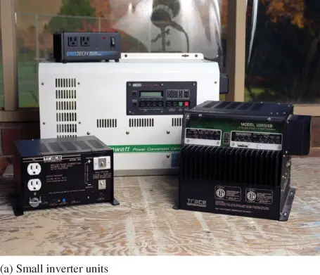
Figure 1a Inverter Units
Some large industrial and commercial inverters are rated to 500 kW, with a few utility-scale inverters rated for over 500 kW. In these cases, the inverter can have an output of several hundred volts.
In many newer systems, the voltage from the array is 1,000 VDC. These high-voltage systems reduce wiring costs and the number of connections, so capital cost is less and losses in cables are less during operation due to lower current.
Modular Inverters System
One method for converting the DC from solar panels to AC in a large array is to use a modular approach in which multiple high-voltage inverters are synched together by a master controller.
An advantage to this method is that inverters can be added as power increases in the middle of the day and then taken offline as sunset approaches. Thus, only the inverters needed are using power. This makes the conversion process more efficient and minimizes runtime on each inverter to extend its life.
It also enables part of the system to be taken offline for maintenance or in case of a problem without taking the entire system offline.
Figure 1b shows 150 kW inverters in a major 4.5-megawatt system that are controlled by a master controller to select inverters depending on the available energy. This particular system has string (series) voltages of up to 1,000 VDC.
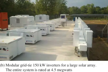
Figure 1b Inverter Units
Basically, an inverter switches the DC output of the energy source on and off and processes the result to create an AC output.
The manner in which switching and processing are done is different for different types of inverters, but typically insulated gate bipolar transistors (IGBT) or metal-oxide-semiconductor-field-effect-transistors (MOSFETs) are used for switching.
These transistors made it possible to develop new power inverters that are much more efficient (some are over 97% efficient) than older analog switching inverters.
There are three basic types of inverters in terms of the type of output: sine wave, square wave, and modified sine wave as shown in Figure 2.
The amplitudes of the modified sine wave and the square wave can be designed to have the same root-mean-square (rms) value as that of the sine wave and, as a result, each of the three waveforms can provide the same power to a load.
Inverters also are available as either grid-tied or non-grid-tied.
Grid-Tied Inverters
Grid-tied inverters provide the option of using power from the electrical grid or providing power to the grid. Grid-tie inverters process the switched waveform and produce a low distortion sine wave output that is compatible with the power company sine wave.
Grid-tied inverters must not only produce a sine wave within acceptable limits; they must also be synchronized to the grid and include automatic disconnect switches as a safety requirement for utility workers in the event the grid goes down. These inverters use switching circuits, including pulse width modulation, to convert from DC to AC.
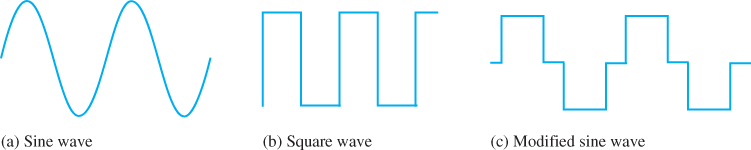
Figure 2 Three Types of Inverter Waveforms Diagram
In addition to these features, most inverters incorporate readouts for voltage and power levels and communication ports to signal system performance characteristics to a controller or computer.
In addition, some inverters are connected to the Internet and can provide a remote user with performance information and diagnostic tools and can even send an email in case of a system error.
Non-Grid-Tied Inverters
Non-grid-tied inverters may have either a no sinusoidal wave or have a sine wave output. They are generally limited to providing power to certain types of loads and are not compatible with the utility company.
The square wave inverter is the simplest and least expensive, but it is seldom used today. One drawback to square wave and modified sine wave inverters is that they tend to produce electrical noise (interference) that can be troublesome for electronic equipment.
The harmonic content of a square wave includes a fundamental sine wave at the frequency of the square wave and a series of odd harmonics.
In general, harmonics are the frequencies contained in a composite waveform, which are integer multiples of the repetition frequency (fundamental).
The fundamental is at the same frequency as the square wave, and each odd harmonic is an odd multiple of the fundamental frequency. Figure 3 shows a fundamental frequency and two odd harmonics that compose a square wave. (There are more odd harmonics that are not shown.)
Available sine wave inverters typically have harmonic distortion less than 3%, which means that the power in harmonics is greatly reduced.
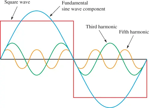
Figure 3 Harmonic Content of a Square Wave
Square Wave Inverter Working
A switching circuit is used in the conversion of DC voltage to an alternating (or bipolar) square wave voltage. One method is the use of the inverter bridge (also known as an H-bridge), which is illustrated in Figure 4.
The switch symbols are used to represent switching transistors (IGBTs or MOSFETs) or other types of electronic switching devices. In Figure 4a, switches S2 and S3 are on for a specified time and S1 and S4 are off.
To produce a 60 Hz square wave, each pair of switches is on for half of the period, which is 8.33 ms.
As you can see, the direct current is through the load, which creates a positive output voltage. In Figure 4b, opposite switches are on and off. The current is in the opposite direction through the load, and the output voltage is negative. The complete on/off cycle of the switches produces an alternating square wave.
The transistors are switched by a timing control circuit, which is not shown for simplicity. The harmonic distortion of a typical square wave output is in the range of 45%, which can be reduced somewhat by filtering out some of the harmonics.
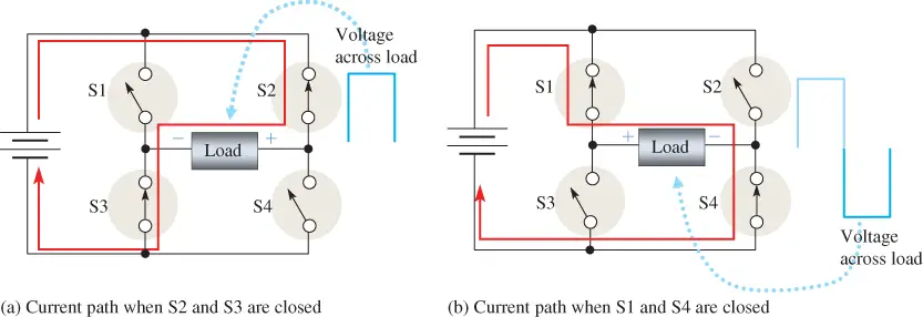
Figure 4 Inverter Bridge. The inverter bridge (H-bridge) is a method of producing a square wave from a DC voltage.
Modified Sine Wave Inverter Working
The operation of a basic H-bridge is enhanced to produce the misnamed modified sine wave, which is shown in Figure 5. (Perhaps modified square wave would be a better name.)
The resulting wave is far from resembling a sine wave despite the name and cannot be used for some types of loads. The wave is created from a square wave and adds a short dead time between positive and negatives excursions of the square wave.
Although the resulting output is definitely not a sine wave, the harmonic distortion is reduced to 24% compared to a pure square wave’s 45%. This is still a significant amount of distortion. Filtering can reduce this distortion; however, filtering also significantly reduces the power to the load and thus reduces the efficiency.
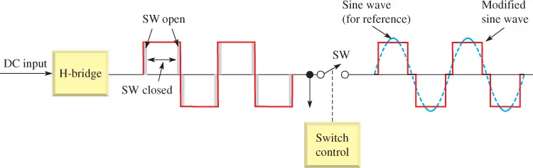
Figure 5 Concept of a Modified Sine Wave Inverter
Note that a so-called modified sine wave with only two levels cannot be used for driving many types of loads, including some electronic devices (some computer power supplies are an exception) and cannot be used to send to the grid.
Appliances that have electronic speed controls (such as mixers) or those with timers may have problems and may be damaged from the modified sine wave.
Also, anything with a motor may not run as efficiently as it would with a pure sine wave. In addition, noise may be generated due to fast transitions in the waveform. This can result in buzzing in speaker systems. As a result of these problems, the modified sine wave has limited use.
By incorporating another level in the two-level modified sine wave, a variation of the modified sine wave is produced that more closely approximates a sine wave, as shown in Figure 6.
This is accomplished by a more complex switching circuit. The result is a reduced harmonic content that has less distortion than the modified sine wave. This waveform is sometimes referred to as a quasi-sine wave, although this term is also sometimes used to describe the two-level modified sine wave.

Figure 6 Three-Level Modified Sine Wave Creating a Quasi–Sine Wave
Single-Phase Sine Wave Inverter Working
Transformerless inverters are much lighter in weight due to the lack of a transformer, and they have higher efficiencies than inverters with transformers.
They are used in Europe but not as much in the United States because of past NEC requirements. Until 2005, the NEC code required all solar electric systems to be negative grounded.
Many electrical engineers voiced concerns about having transformerless electrical systems feed into the public utility grid because of the lack of isolation between the DC and AC circuits.
The square wave, modified sine wave, and quasi-sine wave all have a number of harmonics, which, as you know, are sine waves with frequencies that are odd multiples of the fundamental frequency and different amplitudes.
Harmonics are especially troublesome in some applications, so high-quality sine wave inverters are the most widely used type.
With PWM and low-pass filtering, a nearly pure sine wave can be formed. The PWM process produces a pulse waveform with varying pulse widths proportional to the amplitude of a signal (sine wave in this case).
- In the inverter, a low-power reference 60 Hz sine wave and a higher-frequency triangular wave are used to produce the PWM waveform.
- The sine wave amplitude values are sampled by the triangular wave to produce the PWM waveform.
- The PWM signal is passed through a low-pass filter (equivalent to the mathematical process of integrating) and reproduces the sine wave with very little distortion, as shown in Figure 7.
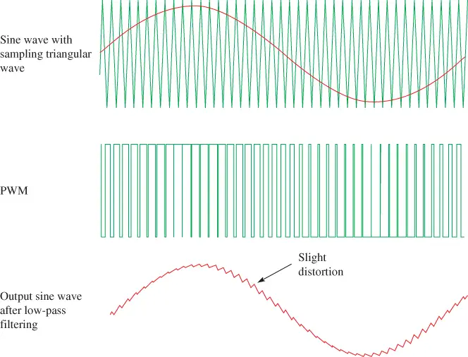
Figure 7 Pulse Width Modulation (PWM) to create a pure Sine Wave
Distortion can be reduced even further by increasing the frequency of the triangular wave relative to the sine wave, but the additional switching can mean a slight loss of efficiency.
A circuit diagram of a single-phase sine wave inverter is shown in Figure 8. Other variations are possible.
Basic Operation of the Sine Wave Inverter
The sine wave inverter uses a low-power electronic signal generator to produce a 60 Hz reference sine wave and a 60 Hz square wave, synchronized with the sine wave.
The reference sine wave goes to the PWM circuit along with a triangular wave that is used to sample the sine wave values to produce a PWM control output. This PWM control signal operates an electronic switch that converts the DC input to a PWM voltage.
The PWM voltage and the 60 Hz square wave are inputs to the H-bridge. The output of the H-bridge is an alternating PWM voltage, as shown in Figure 8.
The filter converts the alternating PWM voltage to a utility-quality sine wave that goes to a transformer that steps it up for use by the load.

Figure 8 Circuit Diagram of a Single-Phase Sine Wave Inverter
Three-Phase Inverter Working
Inverters are available that produce a three-phase output rather than a single-phase output. Homes and small businesses generally use single-phase or split-phase power (two opposite phases).
Three-phase power is used for distribution over the power lines and for customers using large motors and other high-current loads.
Until this point, our discussion has been limited to a single-phase, sinusoidal output, as shown in Figure 9a.
Three-phase power has three sine waves that are each one-third of a cycle (120°) apart, as shown in Figure 9b.
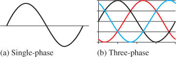
Figure 9 Comparison of Single-Phase Power and Three-Phase Power
Three-phase power is used for electrical distribution because it is very efficient. It is used in industry because three-phase motors and other machines run more smoothly and efficiently and last longer than they would with single phase because the power does not vary over time.
With three-phase power, significantly more power can be delivered with three wires as can be delivered with single-phase using two wires (for the same size wires).
Single Phase Vs Three-Phase Inverter
The basic difference between a single-phase inverter and a three-phase inverter is the type of Inverter Bridge used.
Figure 10 illustrates the concept of a modified inverter bridge used in three-phase inverters. The DC input is processed to produce split-phase PWM voltages that are connected to a three-legged inverter bridge with six transistor switches (mechanical switches are shown for simplicity).
The switch control turns each switch on sequentially for 8.33 ms, which corresponds to a half cycle of a 60 Hz signal.
- The time intervals are all equal; that is, t1 = t2 = t3 = t4 = t5 = t6 = 8.33 ms. For example, switches S1 and S2 are turned on and off alternately for 8.33 ms, creating alternating PWM voltage A.
- Beginning at a precise time during t3 switch S3 is turned on to create a 120° phase shift between PWM voltage A and PWM voltage B.
- Then S3 and S4 are turned on and off alternately, thus creating alternating PWM voltage B.
- Next, at a precise time during t5, switch S5 is turned on to create a 120° phase shift between PWM voltage B and PWM voltage C.
- Then S5 and S6 are turned on and off alternately, thus creating alternating PWM voltage C.
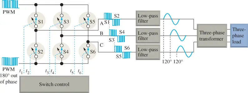
Figure 10 Using a Modified Inverter Bridge for Three-Phase Generation
- The PWM voltages are filtered to produce sine waves, as shown earlier.
- The final output is a three-phase sinusoidal voltage with 120° phase between each of the sine waves. This output is used to drive a balanced three-phase load such as a three-phase motor.
Another way to create a three-phase output is to use three single-phase inverters and a three-phase sync box, as shown in Figure 11.
The sync box introduces a phase shift of 120° between each of the three single-phase inputs and produces a three-phase output synchronized with the grid.
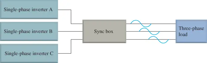
Figure 11 Three-Phase Output Using Three Single-Phase Inverters
Review Questions
- What is the purpose of a DC to AC inverter?
- Name three types of inverters based on their output.
- What does an H-bridge do?
- What is PWM? How is a PWM waveform produced for an inverter?
- What is the difference between single-phase AC and three-phase AC?
- What type of AC power is typically used in residences and small businesses?
- Name one advantage of three-phase over single-phase.
Answers
- The inverter takes the DC output voltage of the batteries or of the energy source and converts it to a standard utility voltage or a three-phase voltage.
- Sine wave, modified sine wave, and square wave
- An H-bridge converts DC to an alternating or bipolar square wave.
- PWM stands for “pulse width modulation.” It produces a pulse waveform with pulse widths proportional to the amplitude of a sine wave by comparing a reference sine wave with a high-frequency triangle wave.
- Single-phase has one ac voltage; three-phase has three AC voltages separated by one-third of a cycle each.
- Single-phase and split-phase; split-phase has two waveforms that are 180 out of phase with each other.
- Three-phase is more efficient for driving large motors and does not require separate starting windings or another starting method.
Inverter and Sine Wave Inverter Working Key Takeaways
Understanding the various types of inverters—sine wave, square wave, and modified sine wave—and their working principles is essential because inverters play a critical role in numerous real-world applications. From powering homes and businesses with renewable energy systems to supporting large-scale solar farms and maintaining grid stability, the efficiency, waveform quality, and compatibility of inverters directly impact system performance and reliability. High-quality sine wave inverters are particularly important where harmonic distortion can damage sensitive electronics or reduce motor efficiency. Modular and grid-tied inverter systems enable scalable, flexible, and smart energy solutions, which are vital for sustainable development and modern power infrastructure.