This guide covers Series RLC Circuit Analysis, Phasor Diagram, Impedance Triangle, Solved Examples and several Review Questions Answers.
A series RLC circuit contains elements of resistance, inductance, and capacitance connected in series with an AC source, as shown in Figure 1.
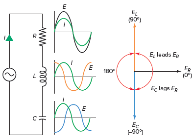
Figure 1 Series RLC circuit diagram

RLC Series Circuit Characteristics
The characteristics of the RLC series circuit can be summarized as follows:
- The current is the same through all components, but the voltage drops across the elements are out of phase with each other.
- The voltage dropped across the resistance is in phase with the current.
- The voltage dropped across the inductor leads the current by 90 degrees.
- The voltage dropped across the capacitor lags the current by 90 degrees.
- The voltages dropped across the resistor, inductor, and capacitor depends on the circuit current and the values of R, XL, and XC:
The three voltages of a series RLC circuit are combined, as shown in the circuit voltage vector (phasor) diagram of Figure 2 and constructed as follows:
- A horizontal reference line representing the common current element is drawn first.
- The voltage across the resistor is in phase with the current and, therefore, is placed directly on the current line.
- The voltage across the inductor leads the current by 90 degrees and so is drawn upward at a 90-degree angle from the current.
- The voltage across the capacitor lags the current by 90 degrees and so is drawn downward at a 90-degree angle from the current.
- To combine the voltages, the two reactive voltage values, which are 180 degrees out of phase with each other, are subtracted.
- The total applied voltage (ET) is the vector sum of the voltage across the resistor (ER) and the difference in voltage between EL and EC. This voltage is computed using the following formula:
![]()
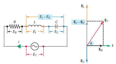
Figure 2 Voltage vector (phasor) diagram for a series RLC circuit.
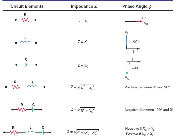
The circuit’s phase angle theta (θ) is always the angle that separates the circuit’s current and the applied voltage source, as summarized in Table 1.
- A series RLC circuit will be inductive and have a positive phase angle when the inductive reactance and resulting voltage across the inductor is greater than the capacitive reactance and the resulting voltage across the capacitor.
- A series RLC circuit will be capacitive and have a negative phase angle when the capacitive reactance and resulting voltage across the capacitor is greater than the inductive reactance and the resulting voltage across the inductor.
Table 1 Series RLC Circuit Phase Angle
Voltage Calculation in Series RLC Circuit Example 1
For the series RLC circuit shown in Figure 3:
- Determine the value of the applied voltage ET.
- Draw a voltage vector diagram for the circuit.
- Is the circuit inductive or capacitive? Why?
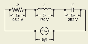
Figure 3 Circuit to example 1.
Solution:
a. $\begin{align}& {{E}_{T}}=\sqrt{E_{R}^{2}+{{\left( {{E}_{C}}-{{E}_{L}} \right)}^{2}}} \\& =\sqrt{{{95.2}^{2}}+{{\left( 252-179 \right)}^{2}}}=120V \\\end{align}$
b. The voltage vector diagram is shown in Figure 4.
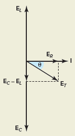
Figure 4 Answer to example 1(b).
c.The circuit is capacitive because voltage across the capacitor is greater than the voltage across the inductor.
Series RLC Circuit Impedance
When XL is greater than XC, the net reactance is inductive and the circuit acts essentially as a RL series circuit. This means that the impedance, which is the vector sum of the net reactance and resistance, will have an angle between 0 and 90 degrees.
Similarly, when XC is greater than XL, the net reactance is capacitive and the circuit acts as a RC series circuit. The impedance, therefore, has an angle somewhere between 0 and 90 degrees. In both cases, the value of the impedance angle depends on the relative values of the net reactance (X) and the resistance (R). The angle can be found by the equation
![]()
Series RLC Circuit Impedance Diagram
The impedance diagram for a typical series RLC circuit, inductive in nature, is shown in Figure 5 and can be summarized as follows:
- The total impedance (Z) is equal to the vector sum of the circuit’s reactance and resistance.
- Since the inductive reactance (XL) and the capacitive reactance (XC) are 180 degrees out of phase, the total net reactance is found first by subtracting the smaller of the two reactive values from the larger.
- The smaller reactance value is canceled out, and the larger value is reduced by the amount of the smaller value.
- The vector sum of the total reactive value (X) and resistance (R) is equal to the impedance and can be computed as follows:
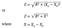
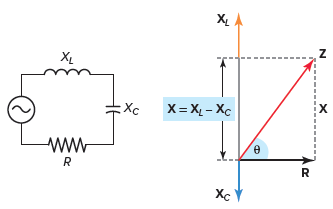
Figure 5 Impedance diagram for a series RLC circuit.
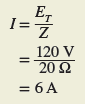
If the impedance and applied voltage of a series RLC circuit are known, the current can be found using the Ohm’s law equation:
![]()
Similarly, once the current is known, the various voltage drops can be found using the Ohm’s law equations:

RLC Series Circuit Calculations Example 2
For the series RLC circuit shown in Figure 6, determine:
- Impedance (Z).
- Current (I).
- Voltage drop across the inductor (EL), capacitor (EC), and resistor (ER).
- The phase angle (θ) of the circuit.
Figure 6 Circuit for example 2.
Solution:
$\begin{align}& a.\text{ }X={{X}_{L}}-{{X}_{C}}=24\Omega -10\Omega =14\Omega \\& Z=\sqrt{{{R}^{2}}+{{X}^{2}}}=\sqrt{{{12}^{2}}+{{14}^{2}}}=18.4\Omega \\\end{align}$
\[b.\text{ }I={}^{{{E}_{T}}}/{}_{Z}={}^{220V}/{}_{18.4\Omega }=12A\]
$\begin{align}& c.\text{ }{{E}_{L}}=I\times {{X}_{L}}=12A\times 24\Omega =228V \\& {{E}_{C}}=I\times {{X}_{C}}=12A\times 10\Omega =120V \\& {{E}_{R}}=I\times R=12A\times 12\Omega =144V \\\end{align}$
\[d.\text{ }\theta ={{\tan }^{-1}}\left( \frac{X}{R} \right)={{\tan }^{-1}}\left( \frac{14}{12} \right)={{49.4}^{o}}\]
Power in a Series RLC circuit
Power in a series RLC circuit is illustrated in Figure 7 and summarized as follows:
- True power is dissipated by the resistive component only and may be calculated using any one of the following equations:
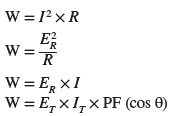
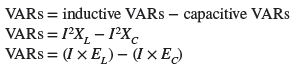
- Reactive power is produced by the circuit’s inductive and capacitive components. Since these two reactive components are 180 degrees out of phase, the net or total volt-amps reactive (VARs) is equal to the difference between the two and may be calculated using any one of the following equations:
- When the supply voltage and current are out of phase because of reactance, the product of the applied voltage and current is called the apparent power and may be calculated as follows:
![]()
- The circuit’s power factor (PF) is equal to the cosine of the angle that separates the circuit’s current and applied voltage. The PF of a series RLC circuit can be found using any of the following equations:

- A lagging power factor means the current lags the applied voltage and is always the case in a series RLC circuit when XL is greater than XC.
- A leading power factor means the current leads the applied voltage and is always the case in a series RLC circuit when XC is greater than XL.
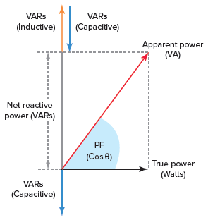
Figure 7 Power Triangle of a series RLC circuit.
Power Calculation in Series RLC Circuit Example 3
From the measurements taken of the series RLC circuit shown in Figure 8, determine:
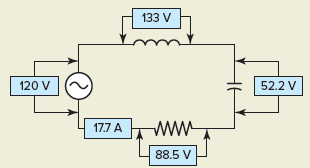
Figure 8 Circuit for example 3.
- True power (W).
- Reactive power (VARs).
- Apparent power (VA).
- Power factor (PF).
- If the power factor is leading or lagging, explain why.
Solution:
$a.\text{ }W=I\times {{E}_{R}}=17.7A\times 8.5V=1566W$
$\begin{align}& b.\text{ }VARs=\left( I\times {{E}_{L}} \right)-\left( I\times {{E}_{C}} \right) \\& =\left( 17.7A\times 133V \right)-\left( 17.7A\times 52.2V \right) \\& =2354-924=1430VARs \\\end{align}$
$c.\text{ }VA={{E}_{T}}\times I=120V\times 17.7A=2124VA$
\[d.\text{ }PF=\frac{W}{VA}=\frac{1566}{2124}=0.737=73.7%\]
e. The circuit is inductive in nature because the voltage across the inductor is greater than that across the capacitor. Therefore, the power factor is said to be lagging.
Impedance Calculation Example 4
For the series RLC circuit shown in Figure 9, determine:
- Impedance (Z).
- Current (I).
- The voltage drop across the resistor (ER), across the inductor (EL) and the capacitor (EC).
- True power (W), Reactive power (VARs), Apparent power (VA).
- Power factor (PF) for the circuit.
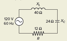
Figure 9 Circuit for example 4.
Solution:
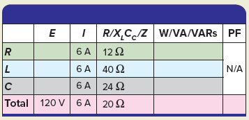
Step 1. Make a table and record all known values.
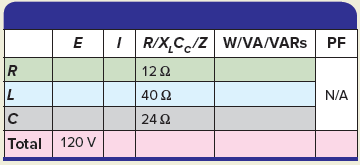
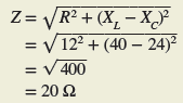
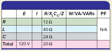
Step 2. Calculate Z and enter the value in the table.
Step 3. Calculate the I and enter the value in the table.
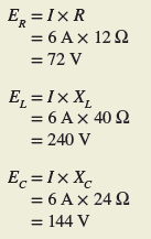
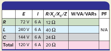
Step 4. Calculate the voltage drop across the resistor (ER), across the inductor (EL), and the capacitor (EC) and enter the values in the table.
Step 5. Calculate the true power (W), reactive power (VARs), and apparent power (VA) and enter the values in the table.
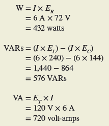
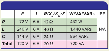
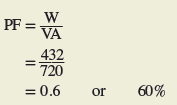
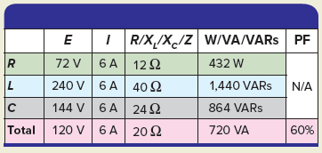
Step 6. Calculate the circuit power factor (PF) and enter the value in the table.
Review Questions
1. For the series RLC circuit of Figure 10, determine:
- The value of the applied voltage.
- The phase angle between the applied voltage and circuit current.
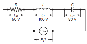
Figure 10 Circuit for review question 3.
2. For the series RLC circuit of Figure 11, determine:
- Impedance.
- Current.
- Voltage drop across the inductor, capacitor, and resistor.
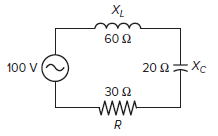
Figure 11 Circuit for review question 4.
3. For the series RLC circuit of Figure 12, determine:
- Current.
- Apparent power.
- Inductive reactive power.
- Capacitive reactive power.
- Net reactive power.
- Power factor.
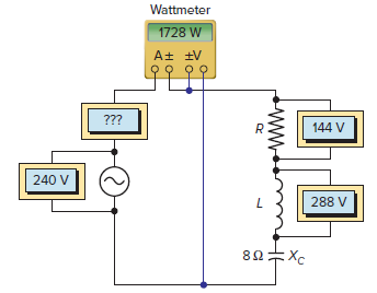
Figure 12 Circuit for review question 3.
4. Complete a table for all given and unknown quantities for the series RLC circuit shown in Figure 13.
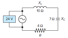
Figure 13 Circuit for review question 4.
Review Questions – Answers
- (a) 54 V, (b) 21.8°
- (a) 50 Ω, (b) 2 A, (c) EL = 120 V, EC = 40 V, ER = 60 V
- (a) 12 A, (b) 2880 VA, (c) 3456 VARs, (d) 1152 VARs, (e) 2304 VARs, (f) 60 %
| E | I | R /XL/XC /Z | W/ VA /VARs | PF | |
| R | 19.2 V | 4.8 A | 4 Ω | 92 W | |
| L | 48 V | 4.8 A | 10 Ω | 230 VARs | |
| C | 33.6 V | 4.8 A | 7 Ω | 161 VARs | |
| Total | 24 V | 4.8 A | 5 Ω | 115 VA | 80 % |