Circuits in which the inductive reactance equals the capacitive reactance (XL=XC) are called resonant circuits. They can be series or parallel circuits and either RLC or LC circuits. The impedance vector for a typical series RLC resonant circuit is shown in Figure 1 and is summarized as follows:
- XL and XC are 180 degrees out of phase.
- XL and XC are equal in value (100 Ω), resulting in a net reactance of zero ohm.
- The only opposition to current is then R (10 Ω).
- Z is equal to R and is at its minimum value, allowing the greatest amount of current to flow.
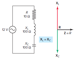
Figure 1 Impedance vector for a series RLC resonant circuit.
The voltage vector for the series RLC resonant circuit is shown in Figure 2 and is summarized as follows:
- The current as determined by Ohm’s law is
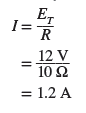
- The same amount of current flows through all components.
- The voltage drop across the inductor is
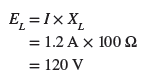
- The voltage drop across the capacitor is
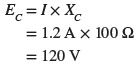
- Voltages across XL and XC are equal (120 V) and 180 degrees out of phase with each other so that each cancels the other.
- With the effects of both the inductor and capacitor canceled out, the only current-limiting component will be the resistor, and the total applied supply voltage appears across the resistor.
- Therefore, the phase angle between the circuit current and the supply voltage will be zero and the power factor will be 1, or 100 percent.
- The circuit can be considered to be purely resistive in nature with inductive reactive VARs of the inductor being canceled out by the inductive capacitive VARs of the capacitor. The true power is
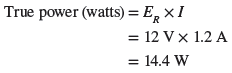
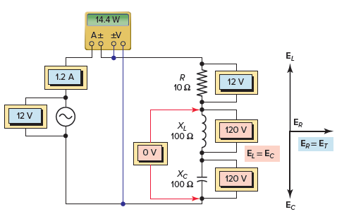
Figure 2 Voltage vector for the series RLC resonant circuit.
Series RLC Resonant Circuit Calculations Example 1
For the series RLC resonant circuit shown in Figure 3, determine:
- Impedance (Z).
- Current (I).
- Voltage drop across the resistor (ER), inductor (EL) and capacitor (EC).
- Apparent, true, and net reactive power.
- Power factor.
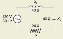
Figure 3 Circuit for example 1.
Solution:
\[\text{a}\text{. Z=R=24 }\!\!\Omega\!\!\text{ }\]
\[\text{b}\text{. I=}\frac{{{\text{E}}_{\text{T}}}}{\text{R}}\text{=}\frac{\text{120V}}{\text{24 }\!\!\Omega\!\!\text{ }}\text{=5A}\]
\[\begin{align}& \text{c}\text{. }{{\text{E}}_{\text{R}}}\text{=I }\!\!\times\!\!\text{ R=5A }\!\!\times\!\!\text{ 24 }\!\!\Omega\!\!\text{ =120V} \\& {{\text{E}}_{\text{L}}}\text{=I }\!\!\times\!\!\text{ }{{\text{X}}_{\text{L}}}\text{=5A }\!\!\times\!\!\text{ 40 }\!\!\Omega\!\!\text{ =200V} \\& {{\text{E}}_{\text{C}}}\text{=I }\!\!\times\!\!\text{ }{{\text{X}}_{\text{C}}}\text{=5A }\!\!\times\!\!\text{ 40 }\!\!\Omega\!\!\text{ =200V} \\\end{align}\]
\[\begin{matrix} Apparent\text{ }Power & ={{E}_{T}}~\times ~I & =120V~\times ~5A=600VA \\ True\text{ }Power & ={{E}_{R}}~\times ~I & =120V~\times ~5A=600W \\ Net\text{ }Reactive\text{ }Power & =\left( I\times {{E}_{L}} \right)-\left( I\times {{E}_{C}} \right) & =0VARs \\\end{matrix}\]
\[\text{e}\text{. Power Factor=}\frac{\text{W}}{\text{VA}}\text{=}\frac{\text{600W}}{\text{600VA}}\text{=1}\]
Recall that inductive reactance varies directly as the frequency of the AC supply voltage (XL=2πfL), while capacitive reactance varies inversely as the frequency (XC=1/2πfC).
When an inductor and capacitor are connected in series in a circuit, there will be one resonant frequency at which the inductive reactance and capacitive reactance will become equal. The reason for this is that as frequency increases, inductive reactance increases and capacitive reactance decreases.
The following formula is used to determine the resonant frequency when the values of inductance and capacitance are known:
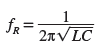
As an example, suppose that a fixed AC voltage of variable frequency is applied to a series RLC circuit. As the frequency of the applied voltage is increased, the inductive reactance XL increases but the capacitive reactance XC decreases, as illustrated in Figure 4. You can see from this graph that at the resonant frequency XL=XC.
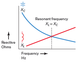
Figure 4 How XL and XC vary with change in frequency.
Resonant Frequency of RLC Series Circuit Example 2
Calculate the resonant frequency of a RLC series circuit containing a 750-mH inductor and a 47-μF capacitor.
Solution:
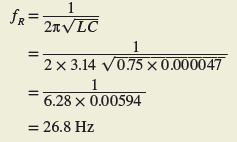
In certain applications a series resonant circuit is used to achieve an increase in voltage at the resonant frequency. As an example, in the series resonant circuit of Figure 5, the voltage across XL and XC is much higher than the applied total voltage. This seemingly impossible condition is caused by the interaction between the capacitor and inductor. The voltage across the inductor and capacitor is 1,200 volts, while the applied voltage is only 120 volts.
In some control applications, the voltage across either XL or XC is used as a signal voltage to perform some function.
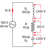
Figure 5 High voltage across reactive elements.
A typical frequency response curve for a series RLC circuit is shown in Figure 6 and summarized as follows:
- The frequency is varied, and the values of current at the different frequencies plotted on the graph.
- The magnitude of the current is a function of the frequency.
- The response curve starts near zero, reaches maximum value at the resonance frequency, and then drops to near zero as the frequency becomes infinite.
- There is a small range of frequencies, called the resonant band or band pass, on either side of resonance where the current is almost the same as it is at resonance.
- The circuit can be used to isolate or filter out certain frequencies.
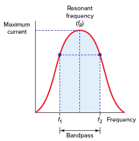
Figure 6 Frequency response curve for a series RLC resonant circuit.
In a series RLC circuit at resonance, the two reactances, XL and XC are equal and canceling. In addition, the two voltages representing VL and VC are also opposite and equal in value, thereby canceling each other out.
Figure 7 compares the circuit condition that exists above or below resonance with that when the circuit is at resonance and is summarized as follows:
- When operating above its resonant frequency, a series RLC circuit has the dominate characteristics of a series RL circuit.
- When operating below its resonant frequency, a series RLC circuit has the dominate characteristics of a series RC circuit.
- When operating at its resonant frequency:
- – Reactance (X) is zero as XL=XC.
- – Impedance is minimum and current is maximum as Z = R.
- – The voltage measured across the two series reactive components L and C is zero.
- – All the supply voltage is dropped across the resistor.
- – The phase angle between the supply voltage and current is zero and the power factor is 1.
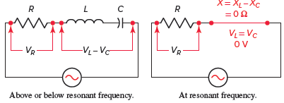
Figure 7 Series RLC resonant circuit characteristics.
Review Questions
- In a series resonant RLC circuit how does the value of XL compare with that of XC?
- Maximum current will flow when a series RLC circuit is at resonance. Why?
- What are the circuit voltage conditions that always exist across the inductor, capacitor, and resistor in a resonant RLC circuit?
- In a series resonant RLC circuit the apparent power (VA) is the same value as the true power (watts). Why?
- State the phase relationship of each of the following for a series resonant RLC circuit:
- XL and XC.
- EL and I.
- EC and I.
- EL and EC.
- R and Z.
- ET and ER.
- Determine each of the following for the RLC circuit shown in Figure 8, when at resonance:
- The resonant frequency.
- The circuit impedance.
- The circuit current.
- The voltage drops across the resistor, inductor and capacitor.
- Net reactive power.
- True power.
- Power factor.
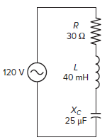
Figure 8 Circuit for review question 6.
7. Answer the following with reference to the circuit shown in Figure 9.
- What is the resonant frequency of the circuit? Why?
- What should the reading on the voltmeter be? Why?
- Assume the frequency of the applied voltage is increased to 400 Hz. Would the circuit become inductive or capacitive? Why?
- Assume the frequency of the applied voltage is decreased to 60 Hz. Would the circuit become inductive or capacitive? Why?
- If the frequency of the applied voltage is increased above 318 Hz, what happens to the value of the impedance and current? Why?
- If the frequency of the applied voltage is decreased below 318 Hz, what happens to the value of the impedance and current? Why?
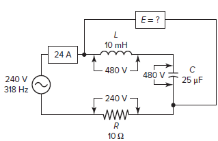
Figure 9 Circuit for review question 7.
8. A series RLC circuit is connected to a variable frequency AC power supply with an ammeter connected to measure current flow and a voltmeter connected to measure the voltage drop across the resistor. Outline how you would proceed to set the circuit to resonance.
9. What should you be aware of when measuring voltages in a series resonant circuit?
10. Give two practical applications for series resonant circuits.
11. A 24-Ω resistor, an inductor with a reactance of 120 Ω, and a capacitor with a reactance of 120 Ω are in series across a 60-V source. The circuit is at resonance. Determine the voltage across the inductor.
Review Questions – Answers
- XL = XC
- At resonance XL is cancelled out by XC so only the resistance limits the current flow in the circuit.
- The voltage across the inductor is equal to that across the capacitor. The voltage across the resistor is the same value as the applied voltage.
- At resonance the reactive power generated by inductance component is cancelled out by the reactive power generated by the capacitance component.
- (a) 180° out of phase, (b) 90° out of phase, (c) 90° out of phase, (d) 180° out of phase, (e) in phase, (f) in phase
- (a) 159 Hz, (b) 30 Ω, (c) 4 A, (d) ER = 120 V, EL = 160 V, EC = 160 V, (e) zero, (f) 480 Watt, (g) 1 or 100%
- (a) The applied 318 Hz is the resonant frequency, because the voltage across the inductor is equal to the voltage across the capacitor.
(b) Zero, because the two voltages EC and EL are of equal value and cancel each other out.
(c) Inductive because XL would become greater than XC.
(d) Capacitive because XC would become greater than XL.
(e) The impedance will increase and the current will decrease because there will be some reactance in addition to resistance limiting the current flow.
(f) The impedance will increase and the current will decrease because there will be some reactance in addition to resistance limiting the current flow.
8. Adjust the frequency of the power supply until the current and voltage across the resistor are at maximum values. This is the resonant frequency.
9. Voltages across XL and XC are equal and 180 degrees out of phase with each other resulting in the circuit to be purely resistive in nature with inductive reactive VARs of the inductor being canceled out by the inductive capacitive VARs of the capacitor.
10. The series resonant circuit can be used to select a particular frequency in a communication circuit or to generate a voltage higher than the supply voltage.
11. 300 volts