This article provides a general overview of circuit breakers, emphasizing their primary function as protective devices and highlighting different types such as miniature circuit breakers (MCBs), molded-case circuit breakers (MCCBs), and air circuit breakers (ACBs), along with their main features and operational mechanisms.
The primary function of a circuit breaker is protection, although it also provides a switching facility. It is widely used to provide protection in its own right but may be used in conjunction with fuses, depending on the service duty required.
Circuit Breaker Types
The most commonly used circuit breaker for rated currents up to 125 A is the miniature circuit breaker (MCB) complying with AS/NZS3111 Approval and test specification— Miniature overcurrent circuit-breakers and AS/NZS 60898 Electrical accessories—Circuit-breakers for overcurrent protection for household and similar installations—Circuit breakers for AC operation.
These standards specify the mean tripping currents and tolerances for classifying these circuit breakers by ‘type’ as shown in Table 1 overleaf.
Table 1 Circuit breaker types and applications
| Miniature circuit breakers (MCB) | 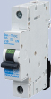 |
Miniature circuit breakers are most commonly used for overload and short-circuit protection of sub-mains and final sub-circuits in domestic and light commercial installations. |
| Molded-case circuit breaker (MCCB) | 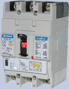 |
Molded-case circuit breakers are most commonly used for the protection of sub-mains, heavily loaded circuits, and final sub-circuits in commercial and industrial installations. They are available with built-in protective relays providing selectable overcurrent settings. |
| Air circuit breaker (ACB) | 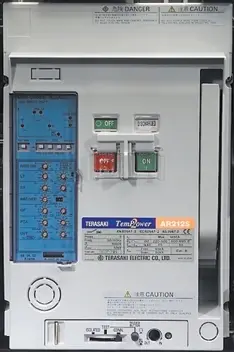 |
Air circuit breakers are used in distribution networks and large installations as main switches for feeders/sub-mains. They commonly have built-in protective relays providing a range of selectable protective and monitoring functions. |
Molded-case circuit breakers (MCCBs) are used for protection circuits in commercial and industrial installations where higher fault conditions and demands exist.
Larger air circuit breakers (ACBs) are used in similar types of installation for high fault current limiting of incoming supply, large feeders (mains and sub-mains), and load switching.
The main features of circuit breakers are shown in Figures 1a, 1b, and 1c overleaf.
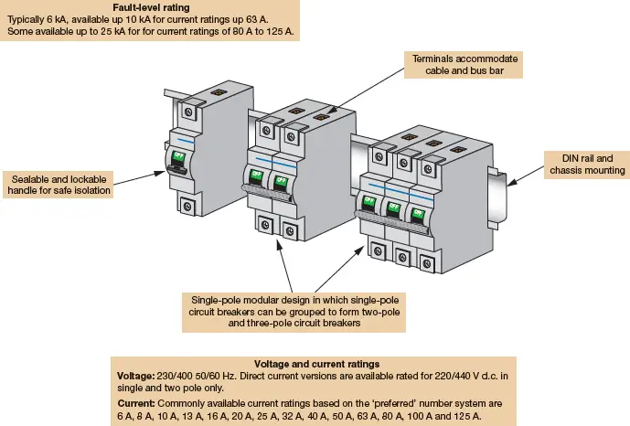
Figure 1a Main features of MCBs
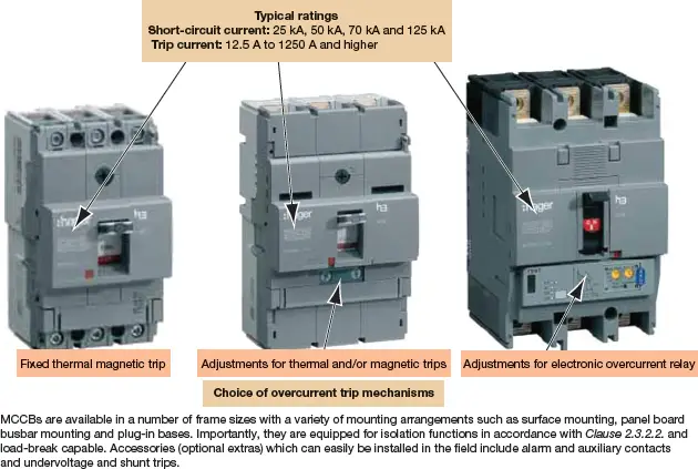
Figure 1b Main features of MCCBs
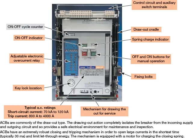
Figure 1c Main features of ACBs
Circuit-Breaker Operation
Protection by a circuit breaker is achieved by automatically opening the circuit (commonly called ‘tripping out’) in response to an overcurrent due either to an overload or short circuit. Modern circuit breakers are ‘thermal-magnetic’ devices, referring to the two tripping elements employed.
The thermal element causes a time-delayed trip of the circuit breaker on detection of overload current while the magnetic element causes an almost instantaneous trip of the circuit breaker on detection of a high inrush current, as is the case with a short circuit. The concept of this arrangement is shown in Figures 1d to 1f.
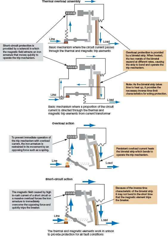
Figure 1d How the overcurrent elements in thermal–magnetic circuit breakers work
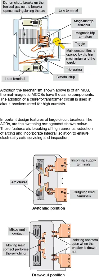
Figure 1e Typical circuit breaker mechanism
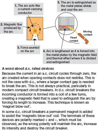
Figure 1f How de-ion arc chutes work
Temperature De-Rating
If the circuit breaker is installed in the same ambient-temperature conditions as the protected circuit, the time to trip will reduce because the ambient temperature of the protected cables will also have risen.
The time lag of the thermal trip ensures that overloads of short duration do not cause tripping; but should these continue, the cumulative heating effect will eventually trip the breaker in time to avoid exceeding the temperature rise limits of the cable.
Did You Know?
What is a shunt trip?
A shunt trip is an additional trip solenoid fitted to a circuit breaker that allows the breaker to be ‘tripped’ from an external switch, button or control device. The shunt trip solenoid activates the mechanical trip release in the same way as the internal thermal and/or magnetic protection units in the breaker cause it to trip. Shunt trips are usually available as an accessory (optional extra) to molded-case circuit breakers and are a standard feature of air circuit breakers.
MCBs are designed and calibrated to carry their rated current and to operate within their designated thermal time/current zone at 30°C in free air conditions. If the circuit breaker is required to operate in a higher ambient temperature than 30°C it will require progressively less current to trip within the designated time/current zone.
In practice, if in an ambient temperature higher than its rating—or even in an enclosure or grouped with other equipment where the temperature will exceed its ‘free air’ temperature rating—the MBC must be de-rated.
One manufacturer provides temperature-correction tables and a factor of 0.9, 0.85 and 0.8 applied respectively for groupings of 2 to 4, 4 to 6 and greater. For example, a 63 A circuit breaker in an enclosure grouped with more than six other circuit breakers would have its rating reduced to 50.4 A. A further reduction in rating would apply if the ambient temperature was higher than 30°C.
Circuit Breaker Characteristics
The two main protection functions of a circuit breaker are to protect wiring from overcurrent, whether an overload or a short circuit—each requires a different time response.
When a short circuit occurs, the protective device must disconnect the supply within 0.4 s for final sub-circuits supplying socket outlets rated up to 63 A, hand-held Class I equipment, and portable equipment intended for manual movement during use.
A maximum disconnect time of 5.0 s is specified for circuits such as sub-mains, final sub-circuits, and those supplying fixed or stationary equipment.
The short-circuit and overload protection functions of circuit breakers are represented in graphs showing their time–current characteristic curves. Fixed-setting circuit breakers (typically MCBs) are intended to protect wiring against both overloads and short circuits in domestic or commercial wiring where operation (switching on or off or resetting) is possible by an uninstructed person.
They are designated by their instantaneous time–current characteristic curves, which classify these circuit breakers into three types as shown in Figure 1g. It is worth noting that the short-circuit function of the modern circuit breaker is a current-limiting characteristic similar to that of an enclosed fuse link (Figure 1h).
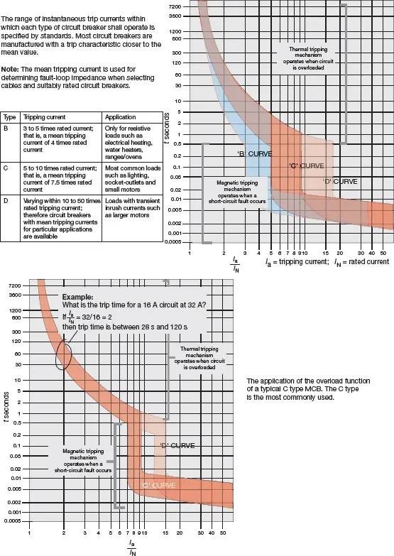
Figure 1g Typical time–current characteristics Curves of circuit breakers
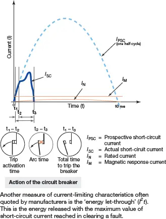
Figure 1h Current-limiting characteristics of a circuit breaker