In this article, we have covered Air Circuit Breaker (ACB) Construction, Six Primary Components, and Working/Operating Principle in detail along with labeled circuit diagrams.
Low-voltage power circuit breakers (LVPCB) are often referred to as air circuit breakers (ACB). Air circuit breakers are typical of the draw-out design, although they can be bolted directly to the bus.
Air circuit breakers are used for applications in which there is a requirement for a more sturdy design than MCCBs and ICCBs offer. See Figure 1. In addition, the circuit breaker can be used as an across-the-line starter for large low-voltage motors.
Air Circuit Breaker (ACB) Construction
Air circuit breakers are completely renewable. That is, they can be rebuilt. Any part that is damaged or compromised can be repaired or replaced. Air circuit breakers have six primary components, which include the following:
- disconnects (stabs)
- contact assemblies
- arc chutes
- operating mechanisms
- OCPDs
- frame and backboard assemblies
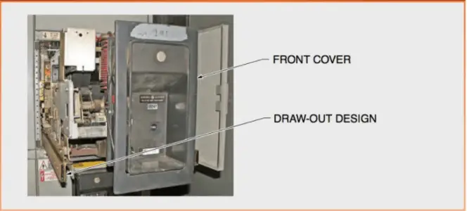
Figure 1. Air Circuit Breaker Labeled Circuit Diagram
- Air Circuit Breaker Disconnects
Circuit breaker disconnects (stabs) are current-carrying components that connect the circuit breaker to the bus or other connections. Disconnects in a circuit breaker include main, secondary, and ground disconnects.
Main Disconnects
Main disconnects connect a circuit breaker to the primary bus and allow load current to flow through the circuit breaker. Air circuit breakers (ACBs) typically use either vertical or horizontal rows of spring-loaded fingers to make contact with the bus bar. Air circuit breakers with high frame ratings (3000 A to 4000 A) often have round (tulip-shaped) main disconnects. The round shape provides more surface area contact and can carry higher load currents than flat bus disconnects. Other types of air-frame circuit breakers with large continuous current ratings have a double row of primary disconnects rather than round disconnects. See Figure 2.
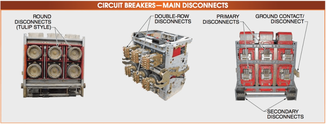
Figure 2. Air Circuit Breaker (ACB) Main Disconnects
If current-limiting fuses are installed on an ACB, the line-side stabs will sometimes be extended farther back from the circuit breaker backboard than the load-side stabs.
On some circuit breakers that use current-limiting fuses, the load-side stabs have extenders installed to make the stab distances from the backboard uniform. The specific arrangement varies from OEM to OEM.
It is typical for ACBs to have a draw-out construction in which the circuit breaker sits in a cradle that can be moved in and out of the enclosure or cubicle. However, ACBs can be bolted directly to the bus as a cost-cutting measure.
Secondary Disconnects
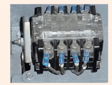
Secondary disconnects are used to bring power into the circuit breaker for such features as the spring-charging motor, indicator lights, and control relays within the circuit breaker. For a low-voltage air circuit breaker, it is typical to connect and disconnect the secondary disconnects as the circuit breaker is racked in and out of its cubicle. See Figure 3.
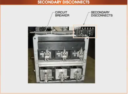
Figure 3. Air Circuit Breaker (ACB) Secondary Disconnects
Ground Disconnects
The frame of an ACB circuit breaker must be connected to the ground bus so that a short circuit or fault will be taken to the ground immediately and the protective devices will operate as quickly as possible. The ground disconnect connects the frame of the circuit breaker to the ground bus. See Figure 4. The connection to the ground disconnect is the first connection made when racking a circuit breaker into the cubicle and is the last connection broken when racking it out of the cubicle. This ensures that the frame of the circuit breaker is grounded whenever there is the possibility of the frame being energized.

Figure 4. Air Circuit Breaker Ground Disconnects
- Air Circuit Breaker Contact Assemblies
Contact assemblies for air circuit breakers include arcing contacts, main contacts, and auxiliary contacts. Contact assemblies can have a butt or bayonet design, depending on the circuit breaker manufacturer’s requirements.
Arcing Contacts
An arcing contact is the contact of a switching device on which an arc is drawn after the main contacts have parted.
Arcing contacts are designed to prevent the main contacts from being damaged as the circuit breaker opens and closes. The arcing contacts on low-voltage circuit breakers are often made of a silver and zinc alloy. Whenever a circuit breaker opens its arcing contacts, some of the contact material melts and some of it vaporizes from the face of the contacts. The amount of material that is eroded depends on the current value being interrupted. This molten and/or vaporized contact material is primarily ejected up into the arc chutes where it can collect. Cleaning this metal spatter is part of a normal preventive maintenance (PM) program.
When the air circuit breaker opens, the main contacts part first and transfer the current to the arcing contacts. The arcing contacts then part and draw the arc across them. When the circuit breaker closes, the arcing contacts make first, which again draws the arc across them. This prevents the main contacts from carrying the arc and preserves them from damage. This also means that the arcing contacts wear/erode long before the main contacts. If the main contacts show any signs of pitting or damage from arcing, the arcing contacts may be misaligned or worn out. See Figure 5.
Arcing contacts often have an arcing horn on the top of the contact structure. The arcing horn aids in transferring the arc from the arcing contact to the arc runner in the arc chute.

Figure 5. Air Circuit Breaker (ACB) Arcing Contacts
Main Contacts
The main contacts in an air circuit breaker are constructed of a softer alloy using less zinc and more silver than arcing contacts. They carry the load current and must have a low impedance to current flow. Main contacts are larger than arcing contacts, which decreases their impedance.
Some circuit breakers also have intermediate contacts. The intermediate contacts are only used on the largest frame air circuit breakers such as the GE AK-50, AK-75, and AK-100. Intermediate contacts act as a second set of arcing contacts. When the main contacts open, the load is transferred to the intermediate contacts and then to the arcing contacts.
Intermediate contacts do not actually make or break the load current. Rather, they transfer the load current from the main contacts to the arcing contacts when opening and from the arcing contacts to the main contacts when closing. Since the intermediate contacts extend just a bit farther than the main contacts, they will make before and break just after the main contacts do. Arcing contacts prevent the main contacts from eroding by drawing the arc across themselves. If the main contacts carried the arc, they would rapidly burn off. This would cause the circuit breaker to restrike, which means it cannot interrupt the arc. A restrike often results in the total destruction of the circuit breaker and switchgear. See Figure 6.
Auxiliary Contacts
Auxiliary contacts supply control power for electrical functions within circuit breakers, such as switching the spring-charging motor on and off, controlling indicator lights, and controlling open/close circuits. With LVPCBs, auxiliary contacts are mounted directly onto the frame of the circuit breakers.
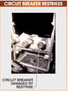
Figure 6. Air Circuit Breaker (ACB) Restrikes
TECH FACT
Auxiliary contacts are designated on drawings as 52a (for normally open contacts) and 52b (for normally closed contacts). The 52a contacts are in the same position as the main contacts of the circuit breaker, while 52b contacts are opposite. When the main contacts are open, 52a contacts are open and 52b contacts are closed.
Air Circuit Breaker (ACB) Auxiliary Contacts
- Low- and Medium-Voltage Circuit Breaker Contact Design
Both arcing and main contacts can be butt- or bayonet-style contacts. Butt-style contacts usually have one flat and one contoured contact face. Some circuit breakers have a combination of butt and bayonet contacts. See Figure 7.
The purpose of the contour is to make a wiping motion when the contacts make. The moving contact hits the stationary contact then makes a wiping motion as it slides along the face of the stationary contact. This wiping motion prevents the contacts from welding together and also cleans the contacts.
In addition, the stationary contacts are usually spring-loaded so that when the moving contact assembly hits the stationary contact assembly, it is pushed backward. This promotes the wiping action and also prevents contact bounce, which would occur if the moving contacts were immobile. When the contacts close, the combination of the compression of the stationary contact and the contoured surface causes a wiping motion against the flat-surface contact without contact bounce.

Figure 7. Air Circuit Breaker (ACB) Contacts Design
Bayonet-style contacts are found on medium-voltage air circuit breakers and late generation LVPCBs. The current-carrying portions of the contacts are on the sides rather than the faces of the contacts. As with butt-style contacts, it is important not to change the shape of the contact faces, as this could cause the circuit breaker to malfunction.
- Air Circuit Breaker Arc Chutes
Arc chutes cool down the electrical arc and extinguish it in four cycles (LVPCBs) to six cycles (medium-voltage air circuit breakers). Because arcs are harder to extinguish in medium-voltage circuit breakers than in low-voltage circuit breakers, extra cycles are required to extinguish arcs.
Air Circuit Breaker (ACB) Working Principle
Modern operating mechanisms are quick to make, quick break, which means that the speed of operation is independent of the speed of the control handle. The modern circuit breaker operating/working mechanisms are called stored energy mechanisms since there are both opening springs and closing springs.
SAFETY TIP
One set of springs in circuit breaker operating mechanisms usually have tension placed on it. For this reason, extreme care must be used when working on or near circuit breaker contacts. They have heavy moving contact assemblies and powerful springs that can cause injury. Even when opening, these devices have such force that they could break bones and lacerate skin. Allow plenty of clearance between any body parts and the moving parts of a circuit breaker. Always wear proper personal protective equipment (PPE) when working with circuit breakers.
One obsolete design includes a simple prop and roller operating mechanism that has an accordion-style linkage to connect the operating mechanism to the contact assemblies. When the circuit breakers close, the closing springs force the contacts closed. At the same time, the prop is lifted onto the top of the roller. The opening springs are now stretched and create an opening force. The prop, by being in the center of the roller, is now in a mechanical bind, since all the opening force is applied through the prop-and-roller centerlines.
To trip the circuit breaker, the prop is knocked off the roller by the trip bar. The prop falls off the roller, the accordion linkage collapses, and the circuit breaker contacts open. This type of operating mechanism is used on older circuit breakers. It is inherently weak and requires the circuit breaker to be larger than necessary. Modern operating mechanisms are more compact, which also makes them stronger and less likely to have problems if maintained properly. Regular disassembly and lubrication are necessary for all circuit breakers in order to ensure that they will function properly. See Figure 8.
- Air Circuit Breaker Frames
The frame of an air circuit breaker supports all circuit breaker components. It is typically made from metal and of an open-air design, which means that it is not part of the insulation system in the same way the frame of an MCCB or ICCB would be.
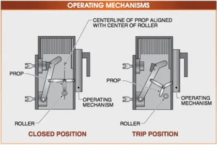
Figure 8. Air Circuit Breaker (ACB) Working Principle/Operating Mechanism
A backboard assembly is the section of a circuit breaker that supports stationary contacts, the primary line, and load disconnects. The backboard assembly is mounted on the circuit breaker frame. Depending on the age of the circuit breaker, the backboard assembly may be composed of slate, polycarbonate, or fiberglass. See Figure 9.

Figure 9. Air Circuit Breaker (ACB) Frame
Air Circuit Breaker (ACB) Key Takeaways
Understanding the construction, components, and working principles of Air Circuit Breakers (ACBs) is essential for professionals involved in electrical systems, particularly in industrial and commercial settings. ACBs offer a reliable and renewable solution for protecting low-voltage power circuits, especially in applications that demand higher durability and operational performance than molded case or insulated case circuit breakers. Their ability to be rebuilt, maintained, and integrated with control and safety features makes them highly suitable for critical infrastructure, motor protection, and power distribution systems. Each component—from disconnects to arc chutes—plays a vital role in ensuring the breaker’s safe and efficient operation, making ACBs an indispensable choice in modern electrical installations where performance, safety, and flexibility are paramount.