The article provides an overview of the two main types of three-phase AC generator and explains their working principles, construction, and electromagnetic field generation. It also discusses how generator output frequency and voltage are determined by factors such as rotor speed, number of stator poles, and magnetic field strength.
There are two basic types of 3-phase generators (alternating-current generators): (1) the revolving-armature type (Figure 1) and (2) the revolving-field type (Figure 2). The 3-phase revolving-armature generator rotates the three single-phase windings, located 120 mechanical degrees apart on the rotor assembly, around the inside of a fixed or stationary electromagnetic field. Because multiple slip-ring/brush assemblies are required to transfer the 3-phase AC power from the three single-phase windings on the rotating member, this type is used the least.

Figure 1. The 3-phase revolving-armature generator
The 3-phase revolving-field generator is constructed by placing the three sets of single-phase windings 120 mechanical degrees apart on a metal core around the inside of a metal housing that supports the core (the stator assembly).

Figure 2. The 3-phase revolving-field generator
As shown in Figure 2, an electromagnet placed in the center of the windings is rotated around the inside of the stator assembly of the three sets of single-phase windings. As the field of the electromagnet cuts across the windings, a voltage is induced into the windings.
An electromagnet is a device consisting of a coil of wire wrapped around a ferromagnetic core. When current flows in the coil of wire, an electromagnetic field is induced in the core. It is a temporary magnet whose magnetic properties are produced from the application of an electrical current.
An electromagnetic field is produced by passing electrical current through the windings of a generator, a motor, a reactor, a solenoid, or a transformer.
The electromagnet in an actual 3-phase AC generator must be excited with a source of direct current to produce the electromagnetic field needed — the strength or intensity of the electromagnetic field is controlled by the magnitude of the field-excitation current.
In Figure 2, the DC excitation voltage is applied to the rotor assembly electromagnet through the two slip-ring — brush assemblies on the rotor shaft of the non-drive end of the generator.
Rotational Synchronous Speed
The illustration in Figure 3 shows the basic concept of a rotating-field 3-phase AC generator and why the three single-phase sine waveforms are also electrically 120 degrees apart.
In Figure 4, the stator frame and interconnected iron pole pieces are shown to give a more accurate illustration of how the windings are arranged: Each phase winding consists of a pole pair.
If the winding of one pole of a given phase is wrapped counterclockwise around the iron pole piece, the winding of the other pole (in the pole pair of each single-phase source) would be wrapped clockwise to give the voltage induced in each single-phase winding the same polarity.
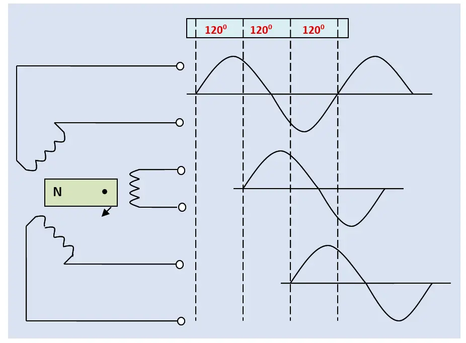
Figure 3. Generation of three 2-wire, single-phase AC, sine waveform electrical supplies
When the North Pole of the rotor assembly’s electromagnetic field is sweeping one pole piece, the South Pole is sweeping the opposite pole piece in the same direction.
The polarity of the rotating iron field poles of the rotor-winding and the direction of wrap of the windings about the stator-winding iron pole pieces both determine the polarity of the induced voltage (direction of current flow when a utilization-equipment load is connected).
With opposite-polarity rotor iron field poles turning in the same direction in the generator and the winding of the two iron pole pieces of each single-phase stator pole pair wrapped in opposite directions, the induced voltages of the pole-pair windings add for a greater value of output voltage in a given single-phase source.
The 3-phase AC generator depicted in Figure 4 is described as a “2-pole generator.” “Two-pole” means there are two poles or one pole pair for each single-phase AC source within the generator. Generators with four, six, or eight poles are not uncommon.
After the windings have been placed on the pole pieces and the pole pieces installed in the metal core, the stationary assembly is referred to as the stator, the stationary member, or the stator assembly of the 3-phase AC generator.
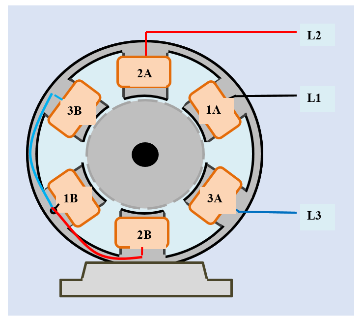
Figure 4. A 2-pole, 3-wire, 3-phase AC generator connected in a wye configuration
The turning of the electromagnetic field of the rotor induces three single-phase AC voltage waveforms of power. As illustrated in Figure 3, the waveform of each pole-pair single-phase winding goes from zero voltage to a positive peak and back to zero voltage with the passing of one rotor field-pole polarity.
In a two-pole machine, the rotor travels through 180 mechanical degrees and the sine waveform of a given phase passes through 180 electrical degrees to form or complete one positive alternation of AC voltage. In the next half revolution or 180 mechanical degrees, with the passing of the opposite magnetic-pole polarity of the rotor field across the same set of single-phase windings, the sine waveform of the given phase goes from zero voltage to a negative peak and back to zero voltage in 180 electrical degrees to form or complete one negative alternation of voltage.
The electromagnetic iron field poles on the rotor assembly made one mechanical revolution of 360 mechanical degrees: One of the single-phase waveforms completed one cycle in 360 electrical degrees.
Remember the three single-phase AC sources are displaced from each other 120 degrees — all will go through their individual complete cycles as the rotor continues to turn. With the start of the second mechanical revolution, the sine waveform of each phase will go through the next positive alternation as the magnetic pole of the rotor’s electromagnet sweeps the respective windings to start another cycle.
AC Generator Frequency
The number of cycles the three single-phase AC sinusoidal waveforms complete in one second is referred to as the frequency of the AC power.
At this point in our discussion, the number of revolutions the rotor electromagnet makes in one second governs the AC output-voltage frequency of the generator (dynamo or AC generator).
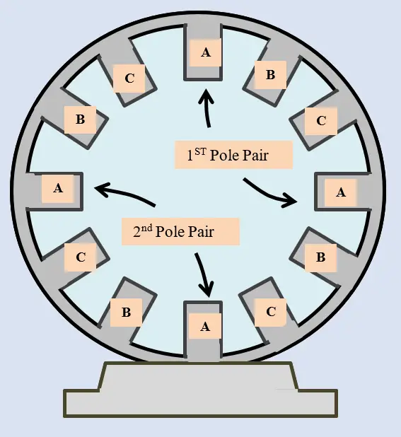
Figure 5. A 4-pole, 3-phase AC alternator
Sixty hertz (Hz) is the standard frequency of the AC electrical power generation, transmission, or distribution system throughout the United States and Canada.
In a 3-phase AC, 60 Hz, electrical power generation system, the rotating electromagnetic field of the stator assembly in the 2-pole, 3-phase AC generator will complete 60 revolutions in one second.
Each single-phase AC source within the 3-phase AC electrical-power generation, transmission, and distribution will electrically cycle (through 3600) 60 times in this same second. In one minute, the rotating electromagnetic field will have completed 3600 revolutions: The rotational synchronous speed of the generator is 3600 rpms.
The output frequency of a 3-phase AC generator is determined by two factors:
(1) The speed of rotation of the rotor and
(2) The number of stator poles.
In a 60 Hz AC electrical-power generation, transmission, or distribution system, 60 electrical revolutions per second divided by 2 for one-half of a mechanical revolution yields 30 mechanical revolutions per second. Multiplied by 60, this 4-pole (two pole pairs per phase), 3-phase AC generator will operate at only 1800 rpms.
As the number of pole pairs is increased, the running speed of the rotating electromagnetic field within the stator assembly is decreased. The rotating speed, which is determined by two principal factors:
(1) The desired frequency of the AC supply and
(2) The number of stator poles
Can be calculated in terms of this simple formula:
S = (120 × f) ÷ P
Where S is the rotating (synchronous) speed of the rotating magnetic field in revolutions per minute
f is the power supply frequency in Hertz (electrical cycles per second)
P is the actual number of poles — not pole pairs — per phase.
Example: If a three-phase AC generator is configured at the point of manufacture as 6-pole will be driven by a prime mover to generate an AC output voltage of 60 Hertz, the synchronous speed of the rotor in the generator is determined as follows:
S = (120 × 60) ÷ 6 = 1200 rpms
Because the number of stator poles is constant for a particular 3-phase AC generator, the output frequency is regulated by controlling the speed of the rotor (the rotating electromagnetic field).
Since 60 Hertz is a standard frequency throughout the United States and Canada, the following list gives the synchronous rotor speeds for 3-phase AC generators with different numbers of poles.
\[\begin{matrix} \text{2 Poles} & {} & \text{3600 RPM} \\ \text{4 Poles} & {} & \text{1800 RPM} \\ \text{6 Poles} & {} & \text{1200 RPM} \\\end{matrix}\]
AC Generator Output Voltage
The readout of an AC voltmeter is referred to as the effective or rms value (root-mean-square value) of the voltage: the effective voltage is affected by both the peak values of the AC voltage waveform and the frequency of repetition. In other words, the output voltage of a 3-phase AC generator is affected by three factors:
- The number of turns (or wraps) of wire in the stator winding,
- The speed of the turning rotor, and
- The strength of the magnetic field in the rotor.
The number of turns of wire in the stator (1) cannot be changed in a particular generator without restructuring and rewinding the stator, and (2) the speed of rotation is generally maintained at a certain level to provide a constant output frequency. Therefore, the magnitude of the output voltage is controlled by increasing or decreasing the strength of the electromagnetic field of the turning rotor (3).
The electromagnetic field strength can be controlled by increasing or decreasing the magnitude of the DC excitation current to the rotor-field winding.
Three-Phase AC Generator Key Takeaways
Understanding the construction, operation, and key parameters of three-phase AC generators is crucial for their effective application across various industries. The ability to control output frequency and voltage by adjusting rotor speed, number of stator poles, and electromagnetic field strength allows these generators to reliably supply consistent and stable power. This is especially important in power generation, industrial machinery, and electrical distribution systems, where precise and efficient three-phase AC power is essential for performance, safety, and equipment longevity.