The article provides an overview of synchronous machine, explaining how they operate as both motors and generators. It highlights their construction, working principles, and the role of excitation and power angle in determining performance and power factor characteristics.
Figure 1 shows a cross-sectional view of a salient-pole synchronous machine. The armature windings are shown as concentrated windings, but in reality, they would be distributed. Such machines can be operated either in Motor or Generator mode.
Motor Operation
For motor operation, a balanced three-phase set of voltages is applied to the armature windings, resulting in the creation of a rotating magnetic field in the air gap between the stator and rotor. The stator and rotor fields combine to create a resultant field. The resultant field is shown external to the machine in Figure 1 for clarity.
The field winding is fed from a DC source either through slip rings or from a rotating rectifier. Thus, the rotor forms an electromagnet with north and south poles, as shown. Of course, whenever we have opposite magnetic poles, we know there will be a force between them. That is the principle of operation of the synchronous motor.
The rotating resultant field essentially pulls the rotor field around with it. As the mechanical load is added to the shaft of the motor, the rotor field tends to fall behind the resultant field by an angle θ, which is referred to as the power angle.
Also, as more load is added to the machine, the armature current increases to provide the extra power required. Note that the speed of the rotating field is fixed by the AC frequency; therefore, the synchronous motor operates only at one speed whether operating at no-load or full-load.
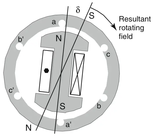
Figure 1 Synchronous machine operating as a motor.
One feature of the synchronous machine is that it has two electrical sources, one for the rotor and one for the stator. Intuitively, it makes sense that as more power is required by the mechanical load on the motor, one or both of the magnetic fields must get stronger. Essentially, either winding can provide exciting current for the machine, which means the power factor of the motor can be varied by controlling the field current. Thus, one of the traditional reasons for using a synchronous motor is to provide power factor correction.
- You May Also Read: Synchronous Machine: Construction and Working
Generator Operation
Figure 2 shows a round-rotor synchronous machine. In this case, as before, a DC voltage is applied to the field winding on the rotor, resulting in DC current and magnetic flux. The magnetic flux is symbolized by the arrows leaving the North Pole and returning to the South Pole. Of course, the magnetic flux forms a closed path through the iron of the stator structure.
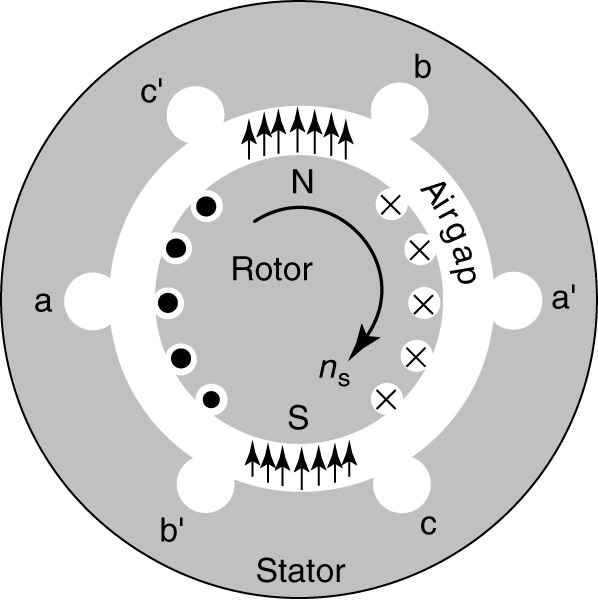
Figure 2 Synchronous machine operating as a generator.
To operate the machine as a generator, the rotor is driven by a prime mover. As the rotating field sweeps by the armature conductors, voltages are induced in the armature windings.
Because the phases are physically 120° apart, the voltages that are induced in the three phases are out of phase by 120° in time. This is a two-pole machine, so one cycle of voltage is induced by each revolution of the machine. To generate constant-frequency voltages, the speed of the machine must be held constant at synchronous speed.
If a balanced, three-phase electrical load is connected to the terminals of the generator, then a balanced set of three-phase currents will flow in the armature windings. That, in turn, will cause a rotating magnetic field, exactly as it did in the motor. The armature field in the generator will lag behind the rotor field by the power angle θ, which varies as the load changes.
Assuming it is connected to the power system, the synchronous generator can draw excitation from the DC field or through the armature winding. So, like the synchronous motor, it can operate at leading or lagging power factors, which enables it to provide reactive power to inductive loads in the power system.
Since a generator provides power, it operates at a lagging power factor when providing power to a lagging power factor load. Thus, a generator provides VAR to the load when operating at a lagging power factor.
Synchronous Machine as Generator and Motor Key Takeaways
Synchronous machines play a vital role in modern electrical systems due to their ability to function efficiently as both motors and generators. Their capability to operate at constant speed, provide power factor correction, and supply or absorb reactive power makes them essential in industrial applications, power generation plants, and grid stability operations, highlighting their importance in both mechanical and electrical engineering fields.