The article provides an overview of three-phase AC power systems, including their configurations, power calculations, and the concepts of true, reactive, and apparent power. It also explains the role of capacitors and inductors in AC circuits and introduces the power factor as a measure of circuit efficiency.
In a three-phase AC power distribution circuit, three single-phase AC sources are interconnected in either a wye or delta configuration to form a 3-wire supply in the alternator, transformer, or electric motor, and sometimes a 4-wire supply in the alternator or transformer.
If the three single-phase AC sources were in-phase with each other, and these single-phase AC sources had equal power ratings, the total power available to a connected load would be the product of the 3-phase AC line voltage times the 3-phase AC line current for any one of the sources multiplied by a factor of 3, but this is not the case.
To use only three circuit conductors instead of the six required for supply and return (2 each) of the three single-phase AC sources, now the three single-phase AC sources are produced at the generating station electrically out-of-phase with each other by a factor of 1200:
Connected in either a wye or delta wiring configuration, the total power of an alternator, motor or transformer (or other 3-phase AC load) is a vector addition instead of a straight algebraic addition.
Because any one single-phase AC source cannot deliver its full rms voltage (root-mean-square or effective AC voltage — equivalent to an equal-work value of DC voltage) when a voltmeter is placed across any two of the three line (phase) conductors, the apparent power of the 3-phase AC electrical-power generation, distribution, or transmission system is increased only by a factor of the √3 (1.732).
Again, assuming equal power ratings of the three single-phase AC sources, the total power available to a connected 3-phase AC load is the product of the 3-phase AC line voltage times the 3-phase AC line current multiplied by the √3. By formula:
Volt-Amps (VA) = √3 × VLINE × A LINE
Or kilo-Volt-Amps (kVA) = (√3 × VLINE × A LINE) ÷ 1000 (/k)
AC Power Triangle
In a DC circuit or in a single-phase resistive AC circuit, the product of line-voltage times the line-current equals the total wattage consumed by the circuit.
In a 3-phase resistive AC circuit, the product of the √3 times the line-voltage times the line-current equals the total wattage consumed by the circuit.
The resistance of a circuit is indicated with an R in both Ohm’s Law [E = I × R, or V = A × R] and Watt’s Power Law [P = I2 × R, or P = A2 × R]. When circuit current flows against the resistance; heat is given off (dissipated) as the wattage (true or active power) of the circuit.
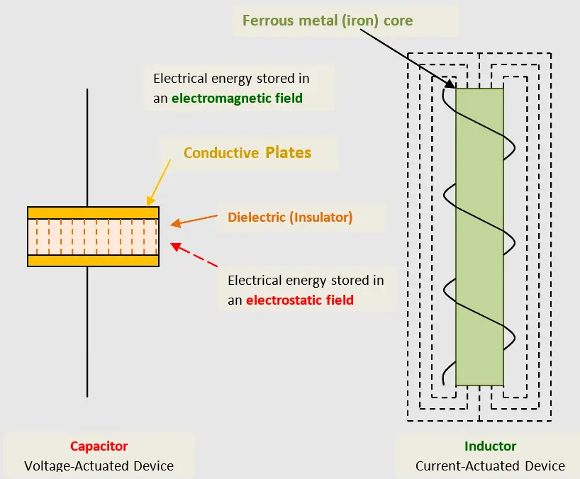
Figure 1. Reactive elements in an AC circuit
All AC circuits — other than purely resistive AC circuits — have another element that offers reactance. Reactance or reactive load is a type of resistance to the flow of electrical current that does not effectively dissipate electrical resistance as heat. Instead, reactance temporarily stores electrical energy in the circuit element. The stored electrical energy is released back into the circuit when circuit conditions (both applied voltage and current drawn) change.
Alternating current is forever changing in magnitude and periodically reversing its direction of current flow. An example of reactance is a car battery that can be charged and discharged on engine starting, and recharged while the engine is running. As shown in Figure 1, the two storing elements in an AC electrical circuit are capacitors and inductors.
A capacitor consists of two conductive plates with an insulating, non-conducting plate (dielectric) between them. A capacitor is labeled or referred to as a voltage device because it stores electrical energy in an electrostatic field across the dielectric between at least two conductive plates or other conductive surfaces.
A capacitor is formed by the grouping of the electrical-circuit supply and return conductors in a common pipe, conduit or another raceway, or in the sheath or armor of a multi-conductor cable. At the standard 60-Hz electrical-power distribution frequency, though, the capacitance of the circuit is minimal: Inductive reactance is the primary reactive component in an AC circuit.
An inductor consists of a wound or spiral-wrapped coil of continuous wire (normally mounted on an iron core). An inductor is labeled or referred to as a current device because it stores electrical energy in an electromagnetic field that surrounds the coil of wire. (The iron core is used to concentrate the “flux lines” or “lines of force” of the electromagnetic field — the surrounding air is not a good conductor of these flux lines.)
An inductor is formed by coiling a given length of wire either over itself, or along the confines of a ferrous metal rod or other metal shapes: Generators or alternators, motors, transformers, solenoids for valves and relays, power contactors, and motor starters, as well as reactor coils, are all inductive loads.
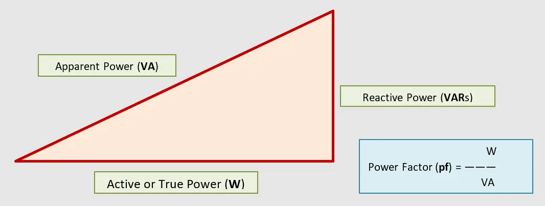
Figure 2. Power relationships in an AC circuit
As shown in the AC power triangle in Figure 2, Wattage, which is represented by the acronym W (watts) or kW (kilowatts ― thousands of watts), is the resistive power (true or active power) of the circuit. Wattage is representative of the work being done, whether it is heat, light, or the turning force of an electric motor.
The power stored in the AC circuit by either the capacitor or the inductor is represented by the acronym VARs (volt-amps reactive) or kVARs (kilo-vars ― thousands of volt-amps-reactive). The stored power, which is returned to the circuit either by the capacitor, when a change in the magnitude of the circuit voltage occurs or by the inductor, when a change in the magnitude of the circuit current occurs, is described as the reactive power.
The apparent power of the AC circuit, shown in Figure 1-17 as the hypotenuse of the power triangle, is determined by measuring the power applied to the circuit with a voltmeter and an ammeter and taking the product of their readings. The apparent power, represented by the acronym of VA (volt-amps) or kVA (kilovolt-amps ― thousands of volt-amps), is the power the supply circuit must deliver to support the connected load. AC power is available as both single-phase and as 3-phase AC.
Power Factor of an AC Circuit
The power factor of an AC circuit (Figure 2) is the ratio of the true power, which is the wattage of the circuit divided by the apparent power of the circuit.
The power factor (pf) will always be a value of 1 or less. By formula:
pf = W ÷ Volt-Amps=P ÷ S
Three-Phase AC Power Calculation Key Takeaways
Understanding the principles behind three-phase AC power systems is essential for designing and managing efficient electrical networks in industrial, commercial, and utility-scale applications. The detailed study of configurations like wye and delta, along with accurate power calculations involving true, reactive, and apparent power, ensures reliable power delivery and minimizes energy losses. Capacitors and inductors play crucial roles in managing reactive power, which directly affects the power factor—a key indicator of system efficiency. By improving power factor and understanding the power triangle, engineers can reduce wasted energy, lower operational costs, and enhance the performance and lifespan of electrical equipment.