The article discusses the equivalent circuit of a synchronous machine, focusing on the generation of voltage (or counter-EMF), armature reaction, and how these elements influence the circuit model. It also explains how to determine the machine’s synchronous reactance using open-circuit and short-circuit tests.
In the Synchronous Machine section, we have seen that there are two rotating magnetic fields in the airgap of the synchronous machine whether it is operating as a motor or as a generator. Any time a magnetic field passes by a conductor, it will induce a voltage in the conductor. Thus, the rotating rotor field will induce a voltage in the armature coils. This is called the generated voltage in a generator or the counter-EMF in a motor (CEMF). Similarly, the rotating field due to the currents in the armature windings will also induce voltages in the stator windings. We will consider each of these cases.
Generated Voltage or C-EMF
We know that the voltage generated in a coil is a function of the magnetic field, the length of the coil and number of turns in it, and the speed that the coil moves through the magnetic flux.
Figures 1(a), (b), and (c) shows a portion of the stator and rotor of a synchronous machine. The rotor is round and contains windings that produce north and south poles, as shown.
The rotor flux leaves the rotor at the North Pole and returns at the South Pole. If the rotor is rotating in the clockwise direction, then the relative motion of the stator coils through the rotor flux is counter clockwise, as shown in Figure 1(a).
Using the right-hand rule for generators, we can determine the direction of the voltage induced in the stator windings. In this case, the coils by the North Pole have a voltage induced that is directed into the page, while the coils by the South Pole have a voltage induced with a polarity pointing out of the page.
The direction of the induced voltages is shown by the dots and crosses above the stator coils.

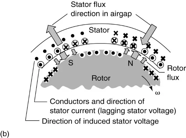
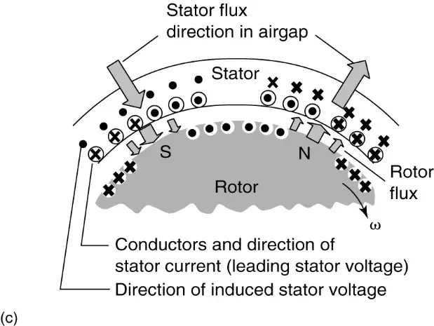
Figure 1: Illustration of the rotor flux and armature reaction flux in a synchronous generator.
- Armature currents in phase with the generated voltage.
- Armature currents lagging generated voltage by 90°.
- Armature currents leading generated voltage by 90°.
The magnitude of the generated voltage in a generator or the CEMF in a motor will be given by
\[\begin{matrix} {{E}_{a}}={{K}_{a}}{{\phi }_{p}}{{n}_{s}} & {} & \left( 1 \right) \\\end{matrix}\]
Where Ka is a constant of the armature winding, ϕp is the flux per pole of the rotor, and ns is the synchronous speed of the rotor.
For constant-frequency AC operation, the synchronous speed is constant, so the only variable that can change the generated voltage, or C-EMF, is the flux per pole. Thus, the excitation of the synchronous machine is used to control the internally generated voltage.
One portion of the equivalent circuit for the synchronous machine is a voltage source that is controlled by the excitation of the field. The remainder of the equivalent circuit is determined by the stator currents.
Armature Reaction
Because the voltages and currents in the stator are AC, there can be a phase angle between them, depending on the power factor at which the synchronous machine is operating. Thus, the direction of the currents in the winding could be in phase with the generated voltage, as shown in Figure 1(a), or the currents could be lagging or leading the generated voltage, as shown in parts (b) and (c) of Figure 1.
The MMF of the stator current creates a second rotating magnetic flux wave in the air gap that induces a voltage in the stator windings. This voltage is called the armature reaction voltage. The armature reaction voltage lags the generated voltage by anywhere from zero to 180°.
In Figure 1(a), the armature current is in phase with the generated voltage, and the flux due to the stator currents lags the rotor field by 90 electrical degrees. Thus, the voltage induced in the armature windings lags the generated voltage by 90°.
The terminal voltage of the synchronous machine would be the sum of the generated voltage and the armature reaction voltage, as shown in Figure 2 (a).
In part (b) of Figure 1, the armature currents are lagging the generated voltage by 90°. In this case, the flux due to the armature reaction directly opposes the field flux, causing an armature reaction voltage 180° out of phase with the generated voltage.
Finally, in part (c) of Figure 1, the armature currents are leading the generated voltage by 90°. The armature reaction flux is in the same direction as the field flux, and the armature reaction voltage component is in phase with the generated voltage.
Figures 2 (b) and (c) show the phasor diagrams corresponding to these latter two cases (part (b) and (c) of Figure 1).
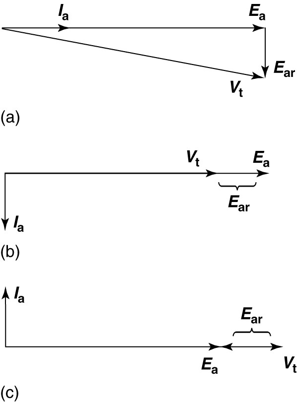
Figure 2: Phasor diagram for a synchronous generator.
- Armature current in phase with the generated voltage.
- Armature current lagging the generated voltage by 90°.
- Armature current leading the generated voltage by 90°.
Neglecting saturation in the steel of the synchronous machine, we can say the armature reaction voltage is proportional to the armature current:
\[\begin{matrix} {{E}_{ar}}={{K}_{a}}{{I}_{a}}{{n}_{s}} & {} & \left( 2 \right) \\\end{matrix}\]
In considering what element to put in the equivalent circuit to account for the armature reaction, we note that the armature reaction provides a voltage similar to an inductive reactance. We also note that the armature current flows through the resistance of the armature winding, which means there will be a resistive voltage drop. Finally, there will be some leakage flux in the armature that does not link the rotor but causes a voltage in the armature winding.
Thus, the per-phase (line-to-neutral) equivalent circuit of the synchronous machine would be as shown in Figure 3 (a). Clearly, the leakage reactance and the armature reaction reactance can be combined. In addition, the resistance of the winding is usually much smaller than the reactance, so it often is neglected.
Figure 3(b) shows the simplified equivalent circuit of synchronous machine in which the combined reactance is designated by Xs and is called the synchronous reactance.
Although our discussion has been in terms of generator operation, the equivalent circuit is the same for both synchronous motor and generator operation, except for the direction of the armature current.

Figure 3: Per-phase synchronous machine equivalent circuit.
- Including armature reactance.
- Simplified, neglecting armature reactance.
Determining the Synchronous Reactance
In order for a model to be of use, there must be some method to determine the parameters of the model, in particular, the synchronous reactance.
Fortunately, we can get an approximate value for the synchronous reactance using two simple tests —the open-circuit and short-circuit tests.
Open-Circuit Test
Looking at the equivalent circuit of Figure 3(b), under open-circuit conditions the terminal voltage of the machine will be equal to the generated voltage. The generated voltage is given by equation 1.
Because the steel of the synchronous machine will eventually saturate, the generated voltage will show the effects of magnetic saturation when plotted as a function of the field current.
The dashed line in Figure 4 shows a plot of the open-circuit voltage of a small synchronous machine. At low values of field current, the open-circuit voltage is essentially linearly related to the field current. At a field current of about 0.45 amps, however, the steel begins to saturate magnetically and the rate of increase in voltage begins to roll off as the field current is increased up to 1.0 amps.
The linear portion of the open-circuit voltage characteristic and its extension, shown by the heavy solid line, is called the air gap line. When operating on the air- gap line, the synchronous reactance is fairly constant.
“By driving the generator at the constant speed with no load and varying the field current, one can obtain the open-circuit characteristic.”
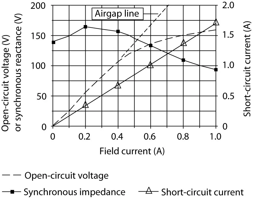
Figure 4: Characteristic curves of a synchronous generator.
Short-Circuit Test
Figure 4 shows the equivalent circuit of the synchronous generator with a short circuit applied at the terminals. Under this condition, all of the generated voltage will be dropped across the synchronous reactance:
\[\begin{matrix} {{E}_{a}}=j{{I}_{sc}}{{X}_{s}} & {} & \left( 3 \right) \\\end{matrix}\]
Where Isc is the short-circuit current.
By applying a short at the terminals of the machine and driving it at rated speed with some excitation, the short-circuit current can be found as a function of the field current. The solid line, marked with triangles, in Figure 4 shows the short-circuit current.
In reality, it is not usually possible to obtain the short-circuit current directly with rated field current, as the armature current would be too high. Thus, only the lower portion of the characteristic is measured directly, and the resulting line is extended to rated field current.
In the case shown in Figure 4, the field current was raised only to 0.25 amps when the short was applied to the synchronous machine terminals. The remainder of the curve was linearly extrapolated.
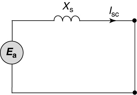
Figure 4: Equivalent circuit of the synchronous machine with short applied at terminals.
Equation 3 can be solved for the synchronous reactance:
\[\begin{matrix} {{X}_{s}}=\frac{{{E}_{a}}}{{{I}_{sc}}} & {} & \left( 4 \right) \\\end{matrix}\]
“It is important to ensure that the generated voltage and the short-circuit current used in equation 4 are both measured at the same value of field current.”
Because the generated voltage is a nonlinear function of the field current, the value calculated for the synchronous reactance will depend on the field current. The solid curve, marked by solid squares, in Figure 4 shows the variation of the calculated synchronous reactance.
Synchronous Machine Equivalent Circuit Key Takeaways
Understanding the equivalent circuit of a synchronous machine—including generated voltage (or counter-EMF), armature reaction, and synchronous reactance—is essential for accurately predicting and controlling the machine’s performance in real-world applications. These parameters directly influence voltage regulation, power factor correction, and system stability in both motor and generator operations. By conducting open-circuit and short-circuit tests, engineers can estimate the synchronous reactance and design systems that operate efficiently under varying load conditions. This knowledge is crucial for power generation, industrial motor drives, and grid-connected operations where precise voltage control, synchronization, and power delivery are critical.