The article explores the principles and analysis of series circuit, discussing their configuration, characteristics, and applications. It covers key topics like equivalent resistance, current and voltage behavior, Kirchhoff’s Voltage Law, power dissipation, and special cases such as open and short circuits, providing equations, examples, and practical insights for understanding and designing series circuits.
Series Circuit Definition
Resistors are stated to be in series configuration once they are linked in such a way that there is ONLY one path for current flow which means that the current stays the same in all parts of the series circuit.
Series Circuit Characteristics
- The voltage drop across each element of a series circuit depends on the element resistance as well as the current level. Two or more series connected resistors can be used as a voltage divider. The potentiometer is an adjustable resistor used as a variable voltage divider.
- The total power supplied to a series circuit is the sum of the power dissipated in the individual components.
- Resistors may be connected in series with an electrical component for the purpose of voltage dropping or current limiting.
How to Calculate Equivalent Resistance in a Series Circuit
The circuit diagram for three series-connected resistors and a voltage source is shown in Figure 1.
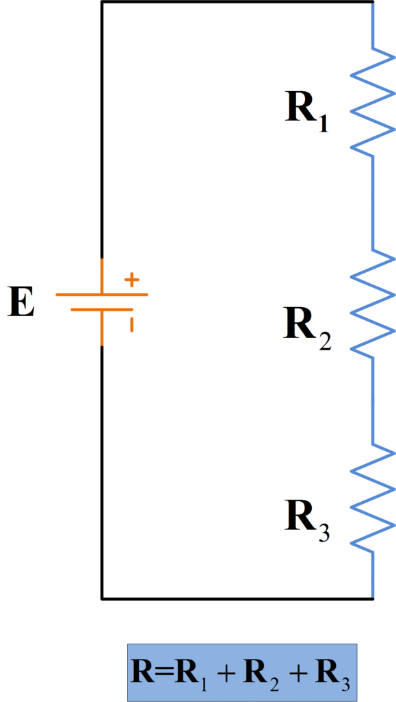
Figure 1. Circuit Diagram of Battery and Series-Connected Resistors
The total resistance connected across the voltage source is:
$R={{R}_{1}}+{{R}_{2}}+{{R}_{2}}$
This is also called the equivalent resistance of the series circuit. For any series circuit with n resistors, the equivalent resistance is
$\begin{matrix} R={{R}_{1}}+{{R}_{2}}+{{R}_{2}}+\cdots +{{R}_{n}} & \cdots & (1) \\\end{matrix}$
For a circuit consisting of n equal value resistors
$R=n*{{R}_{1}}$
The equivalent circuit for the series resistance circuit is illustrated in Figure 2. The equivalent circuit simply consists of the voltage source and the equivalent resistance.
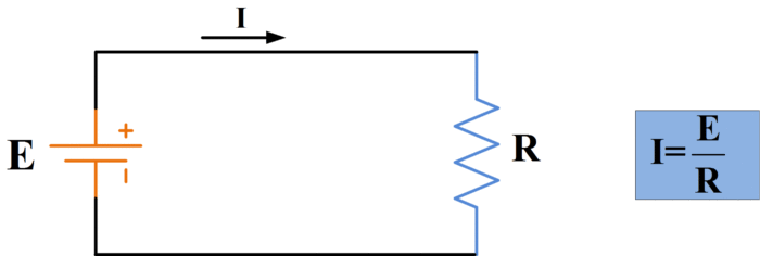
Figure 2. Equivalent Resistance Circuit
How to Find Current in a Series Circuit
An ammeter connected to measure the current flowing in a series circuit is shown in Figure 3.
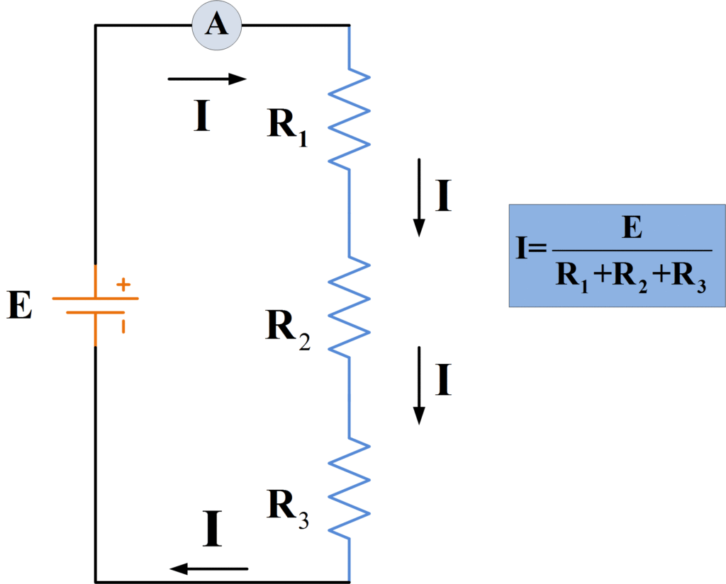
Figure 3. Current Level is the Same in All Parts of the Circuit
- You May Also Read: Parallel Circuit Definition & Parallel Circuit Examples
Because the resistors are connected end-to-end, there is only one path for current flow in the circuit. Current flows from the positive terminal of the voltage source, through the ammeter, and into the top terminal of resistor R1. Clearly, all of the current that flows into the one end of R1 must flow out of the other end. So, the current flows out of the bottom terminal of R1 into the top terminal of R2, and from R2 it moves through R3 to the negative terminal of the voltage source. Thus it is seen that
The current is the same in all parts of a series circuit.
Using ohm’s law, the current through the series circuit is calculated as
\[\begin{matrix} I=\frac{E}{{{R}_{1}}+{{R}_{2}}+{{R}_{2}}+\cdots +{{R}_{n}}} & \cdots & (2) \\\end{matrix}\]
How to Calculate Voltage Drop in a Series Circuit
The three-resistor series circuit is reproduced again in Figure 4 with the addition of a voltmeter to measure the voltage drop across R1.
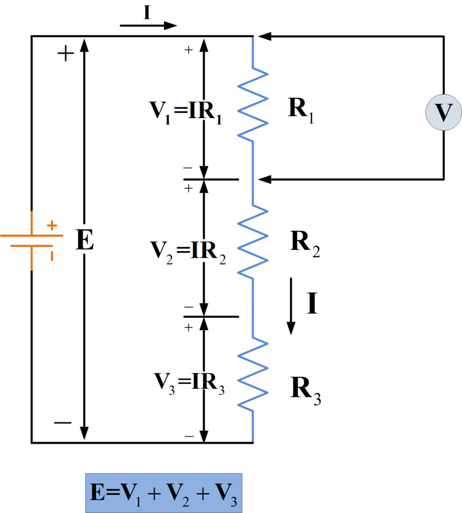
Figure 4. The Supply Voltage Equals the Sum of the Resistor Voltage Drops
It is seen that the current flow causes a voltage drop, or potential difference, across each resistor. If there was no potential difference between the terminals of each resistor, there would be no current flow. Using Ohm’s law, the voltage drops across each resistor are,
\[{{V}_{1}}=I{{R}_{1}},\text{ }{{V}_{2}}=I{{R}_{2}},\text{ }and\text{ }{{V}_{3}}=I{{R}_{3}}\]
Note that the polarity of the resistor voltage drops is always such that the (conventional) current direction is from positive to negative. Thus for the circuit, as shown, the polarity is positive at the top of each resistor, – at the bottom. The sum of the resistor voltage drops is V1+V2+V3, and, as shown in figure 4, this must be equal to the applied emf E. For any series circuit,
$E={{V}_{1}}+{{V}_{2}}+{{V}_{3}}+\cdots +{{V}_{n}}$
Or
$\begin{matrix} E=I{{R}_{1}}+I{{R}_{2}}+I{{R}_{3}}+\cdots +I{{R}_{n}} & \cdots & (3) \\\end{matrix}$
Therefore the total voltage drop will be,
$\begin{matrix} E=I({{R}_{1}}+{{R}_{2}}+{{R}_{3}}+\cdots +{{R}_{n}}) & \cdots & (4) \\\end{matrix}$
Kirchhoff’s Voltage Law
The relationship between the applied emf and the resistor voltage drops in a series circuit is defined by Kirchhoff’s Voltage law:
[stextbox id=’info’ caption=’KVL Definition ‘]In any closed electric circuit, the algebraic sum of the voltage drops must equal the algebraic sum of the applied EMFs.[/stextbox]
Series Circuit Example with Ohm’s Law
Using the following values, determine the voltage drops across each resistor in the circuit of figure 4.
$\begin{matrix} \begin{matrix} {{\text{R}}_{\text{1}}}\text{=15 }\!\!\Omega\!\!\text{ } & {{\text{R}}_{\text{2}}}\text{=25 }\!\!\Omega\!\!\text{ } \\\end{matrix} & {{\text{R}}_{\text{3}}}\text{=5 }\!\!\Omega\!\!\text{ } & \text{E=9V} & \text{I=0}\text{.2A} \\\end{matrix}$
Solution
Voltage drop across each resistor would be;
$\begin{align} & {{V}_{1}}=I{{R}_{1}}=0.2A*15\Omega =3V \\ & {{V}_{2}}=I{{R}_{2}}=0.2A*25\Omega =5V \\ & {{V}_{3}}=I{{R}_{3}}=0.2A*5\Omega =1V \\ & finally, \\ & E={{V}_{1}}+{{V}_{2}}+{{V}_{3}}=9V \\\end{align}$
Series-Connected Voltage Sources
The three-series connected voltage cells in Figure 5 are arranged so that they all produce current in the same direction when applied to a circuit.
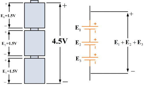
Figure 5. Voltage Sources Connected Series-Aiding
The terminal voltages add together to give
$E={{E}_{1}}+{{E}_{2}}+{{E}_{3}}$
Because the voltage sources assist one another to produce current, they are said to be connected series-aiding. In figure 6, the bottom cell of the three has its negative terminal connected to the negative terminal of the middle cell.
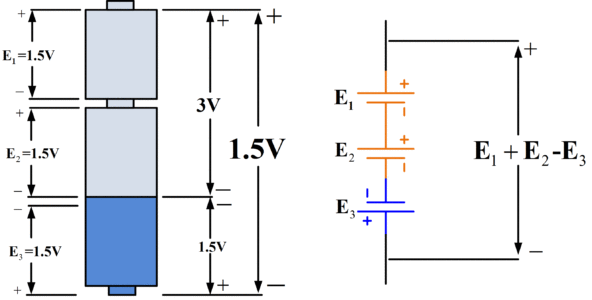
Figure 6. Voltage Sources Connected Series-Aiding and Series-Opposing
Thus, as illustrated by the circuit diagram for the cells, the total voltage is
$E={{E}_{1}}+{{E}_{2}}-{{E}_{3}}$
Because of its terminal polarity, the bottom cell will attempt to produce the current in the opposite direction to that from the other two. Consequently, the bottom cell is connected series-opposing with the top two cells.
When more than one battery or another source of emf is involved, Kirchhoff’s voltage law still applies. Consequently, for the circuit shown in figure 7,
${{E}_{1}}+{{E}_{2}}=I{{R}_{1}}+I{{R}_{2}}+I{{R}_{3}}+I{{R}_{4}}$
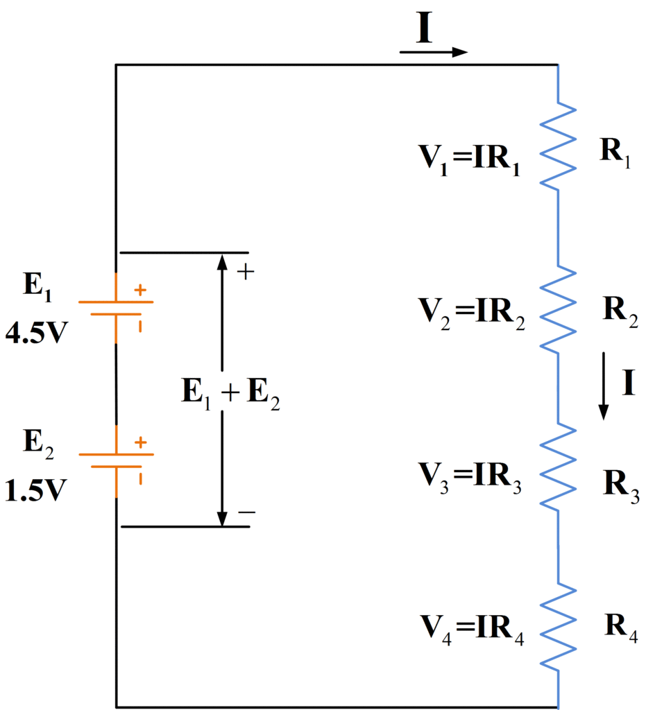
Figure 7. Circuit Diagram of Resistors with Series-Aiding Voltage Sources
The voltage equation for the circuit in Figure 8 is
${{E}_{1}}-{{E}_{2}}=I{{R}_{1}}+I{{R}_{2}}+I{{R}_{3}}+I{{R}_{4}}$
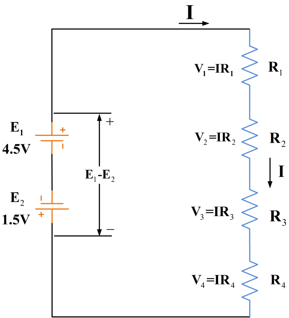
Figure 8. Circuit Diagram of Resistors with Series-Opposing Voltage Sources
How to Solve a Series Circuit
- Determine the total applied voltage E=E1+E2+…
- Calculate the total series resistance, Equation (1)
- Calculate the circuit current, Equation (2)
- Determine the voltage drop across each component:
\[{{V}_{1}}=I{{R}_{1}},\text{ }{{V}_{2}}=I{{R}_{2}},\text{ etc}\]
Series Circuit Example for Series-Aiding Case
The four resistors in figure 7 have the following values:
R1=5Ω, R2=5Ω, R3=5Ω, and R4=5Ω. The emf are E1=4.5V and E2=1.5V. Determine the circuit current and the resistor voltage drops.
Solution
Step 1: Determine the total applied voltage
${{E}_{1}}+{{E}_{2}}=4.5V+1.5V=6V$
Step 2: Calculate the total series resistance
${{R}_{1}}+{{R}_{2}}+{{R}_{3}}+{{R}_{4}}=5\Omega +13\Omega +25\Omega +17\Omega =60\Omega $
Step 3: Calculate the circuit current
\[I=\frac{{{E}_{1}}+{{E}_{2}}}{{{R}_{1}}+{{R}_{2}}+{{R}_{3}}+{{R}_{4}}}=\frac{6}{60}=0.1A\]
Step 4: Determine the voltage drop across each component:
$\begin{align} & {{V}_{1}}=I{{R}_{1}}=0.1A*5\Omega =0.5V \\ & {{V}_{2}}=I{{R}_{2}}=0.1A*13\Omega =1.3V \\ & {{V}_{3}}=I{{R}_{3}}=0.1A*25\Omega =2.5V \\ & {{V}_{4}}=I{{R}_{4}}=0.1A*17\Omega =1.7V \\ & finally, \\ & E={{V}_{1}}+{{V}_{2}}+{{V}_{3}}+{{V}_{4}}=6V \\\end{align}$
Voltage Divider Circuit and Equations
It has been shown that the voltage drops across a string of resistors add up to the value of the supply emf E. Another way of looking at this is that the applied emf is divided up between the series resistors. Figure 9 shows two series connected resistors used as a voltage divider or potential divider.
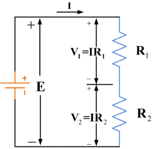
Figure 9. Voltage-Divider Circuit Diagram
From previous results,
$I=\frac{E}{R{}_{1}+{{R}_{2}}}$
Also,
\[{{V}_{1}}=I{{R}_{1}}\]
Therefore,
\[{{V}_{1}}=\left( \frac{E}{{{R}_{1}}+{{R}_{2}}} \right)*{{R}_{1}}\]
Or we can simply write
\[\begin{matrix} {{V}_{1}}=\left( \frac{{{R}_{1}}}{{{R}_{1}}+{{R}_{2}}} \right)*E & \cdots & (5) \\\end{matrix}\]
Also if,
${{R}_{1}}={{R}_{2}}$
Then,
\[{{V}_{1}}={{V}_{2}}=\frac{E}{2}\]
When more than two series resistors are involved, the voltage drop across any one resistor Rn is:
$\begin{matrix} {{V}_{n}}=\left( \frac{{{R}_{n}}}{{{R}_{1}}+{{R}_{2}}+{{R}_{3}}+\cdots } \right)*E & \cdots & (6) \\\end{matrix}$
When there are n equal value resistors in series
\[{{V}_{1}}={{V}_{2}}=\cdots ={{V}_{n}}=\frac{E}{n}\]
Voltage Divider Theorem
In a series circuit, the voltage drop across a particular resistor is the source voltage times the ratio of that resistor’s value to the total series resistance.
The voltage-divider theorem illustrated by equation 5 and 6 is important because it is applied over and over again in electronic circuits. A surprisingly large amount of electronic circuit designs is merely a selection of appropriate resistor values for voltage-divider networks.
How to Find Power in a Series Circuit
In a series circuit, it is possible to calculate the power dissipated in a resistor from a knowledge of any two of the three quantities: current, voltage, and resistance. Thus, in Figure 10, the power dissipated in R1 is:
\[\begin{matrix} {} & {{P}_{1}}={{V}_{1}}I \\ \begin{matrix} or \\ or \\\end{matrix} & \begin{matrix} {{P}_{1}}=\frac{V_{1}^{2}}{{{R}_{1}}} \\ {{P}_{1}}={{I}^{2}}{{R}_{1}} \\\end{matrix} \\\end{matrix}\]
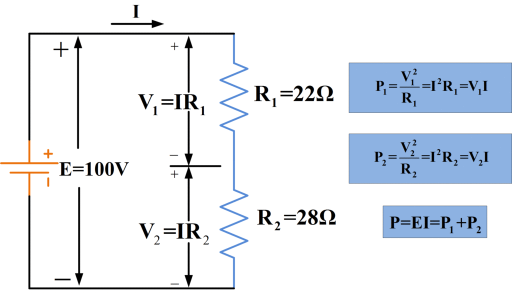
Figure 10. Power Dissipation in Series Connected Resistors
The power dissipated in R2 is calculated in exactly the same way, and the total power dissipated in the circuit is the sum of the individual resistor power dissipation.
For any series resistance circuit, the total power dissipated is
\[\begin{matrix} {{P}_{1}}={{P}_{1}}+{{P}_{2}}+{{P}_{3}}+\cdots +{{P}_{n}} & \cdots & (7) \\\end{matrix}\]
And
\[\begin{align} & P={{V}_{1}}I+{{V}_{2}}I+{{V}_{3}}I+\cdots +{{V}_{n}}I \\ & P=I({{V}_{1}}+{{V}_{2}}+{{V}_{3}}+\cdots +{{V}_{n}}) \\ & P=IE=Supply\text{ }Power \\\end{align}\]
The total power can also be calculated as
\[\begin{matrix} P=\frac{{{E}^{2}}}{{{R}_{1}}+{{R}_{2}}+{{R}_{3}}+\cdots +{{R}_{n}}} & \cdots & (8) \\\end{matrix}\]
Where E is the supply voltage.
Also,
\[\begin{matrix} P={{I}^{2}}({{R}_{1}}+{{R}_{2}}+{{R}_{3}}+\cdots +{{R}_{n}}) & \cdots & (9) \\\end{matrix}\]
Power Dissipation in Series Circuit Example
Determine the total power dissipated and the power dissipation in each resistor in figure 10 when V1=44V and V2=56V.
Solution
\[\begin{align} & {{P}_{1}}=\frac{V_{1}^{2}}{{{R}_{1}}}=\frac{{{(44)}^{2}}}{22}=88W \\ & Similarly, \\ & {{P}_{2}}=\frac{V_{2}^{2}}{{{R}_{2}}}=\frac{{{(56)}^{2}}}{28}=112W \\\end{align}\]
For total power,
\[\begin{align} & P={{P}_{1}}+{{P}_{2}}=88+112=200W \\ & or \\ & P=\frac{{{E}^{2}}}{{{R}_{1}}+{{R}_{2}}}=\frac{{{(100)}^{2}}}{22+28}=200W \\\end{align}\]
Resistor Power Rating
The physical size and type of construction of a resistor determine the maximum power that it may dissipate. The maximum power that may be dissipated safely in any component is specified by the manufacturer and it is referred to as its power rating.
A wide range of resistors is available with various power ratings. Typical ratings for resistors employed in electronic circuits are: 1/8 W, ¼ W, ½ W, and 1 W. the power ratings for small potentiometers and variable resistors typically ranges from ½ W to 5W. Every time the value of a resistor is calculated for a particular application, its power dissipation should also be determined. Where a component power dissipation exceeds its rating, the component is likely to burn out.
Voltage Dropping and Current Limiting
Sometimes a resistor is included in series with an electronic device to drop the supply voltage down to a required level. In other circumstances, this kind of arrangement can be thought of as a current limiting resistor.
In the circuit shown in Figure 11, series resistor Rs limits the current to an electronic device that operates at a voltage level lower than the source voltage. In Figure 12, Rs provides a voltage drop to three series-connected lamps. It can also be shown that Rs limits the current to the level required by the three lamps.
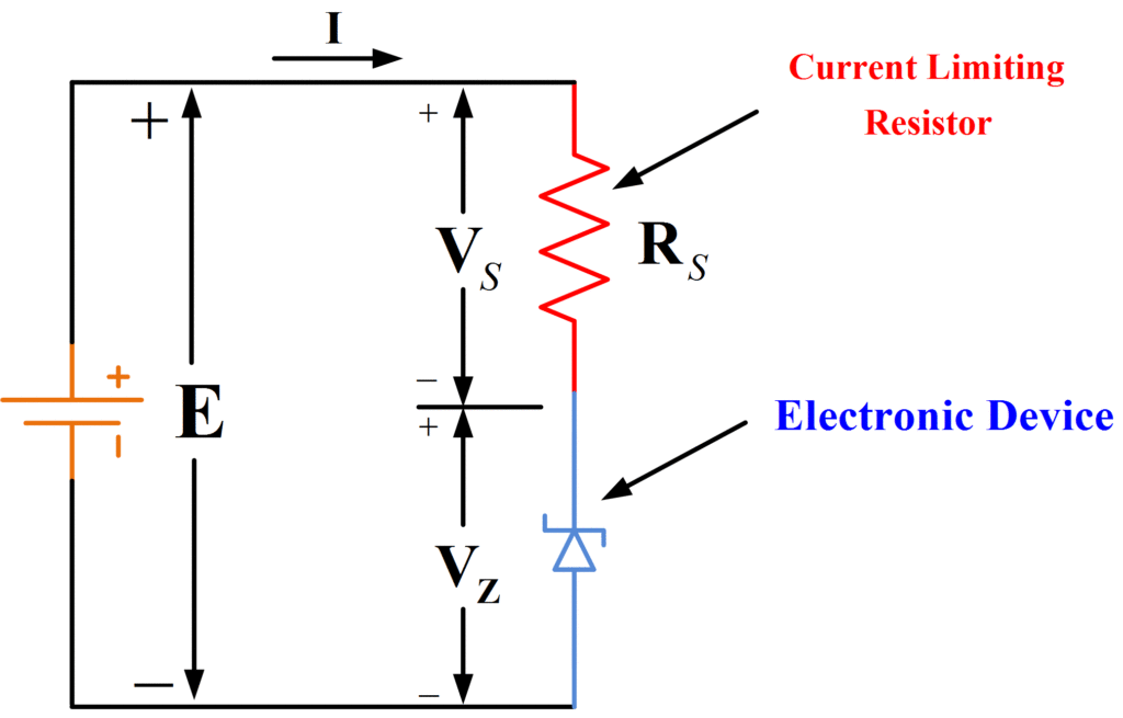
Figure 11. Use of a Current Limiting Resistor
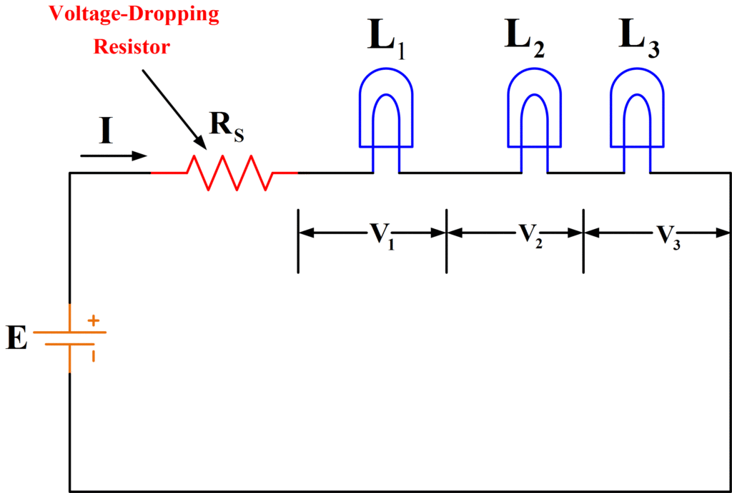
Figure 12. Use of a Voltage Dropping Resistor
Open Circuit and Short Circuit in a Series Circuit
An open-circuit occurs in a series resistance circuit when one of the resistors becomes disconnected from an adjacent resistor as shown in Figure 13. An open-circuit can also occur when one of the resistors has been destroyed by excessive power dissipation.
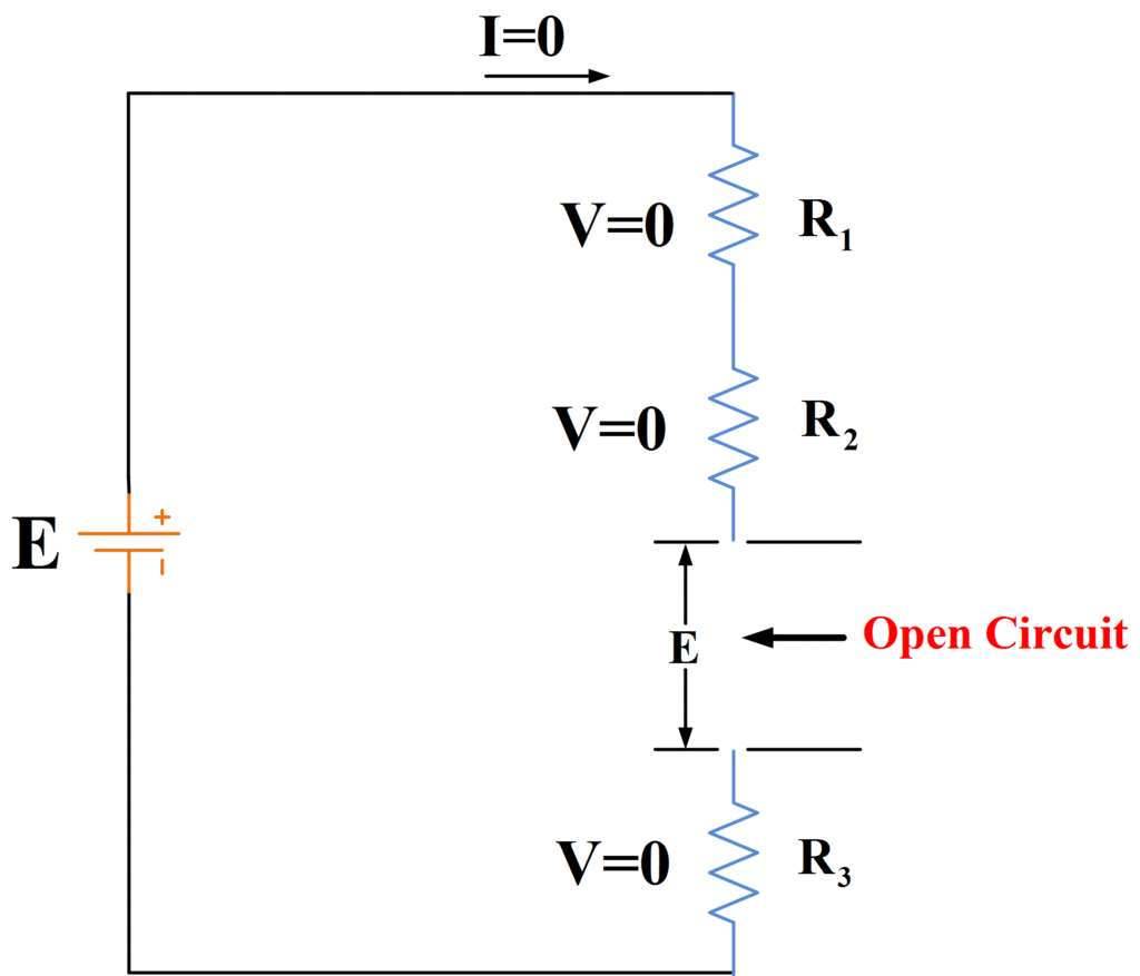
Figure 13. Circuit Diagram of Series Circuit with an Open-Circuited Connection
In the circuit of figure 13, the open-circuit can be thought of as another resistance in series with R1, R2, and R3. Thus instead of the current being
\[I=\frac{E}{{{R}_{1}}+{{R}_{2}}+{{R}_{3}}}\]
It becomes
\[I=\frac{E}{{{R}_{1}}+{{R}_{2}}+{{R}_{3}}+{{R}_{oc}}}\]
Suppose that Roc=100,000 MΩ and E=100V; then, with Roc>> (R1+R2+R3),
\[I=\frac{100V}{100,000M\Omega }=1nA\]
This small amount causes an insignificant voltage drop along R1, R2, and R3. With virtually zero voltage drop across the resistors, the voltage at the open circuit is
${{V}_{oc}}=E$
Figure 14 shows a series resistance circuit with resistor R3 short-circuited. In this case, the resistance between the terminals of R3 is effectively zero. Consequently, instead of the current being
\[I=\frac{E}{{{R}_{1}}+{{R}_{2}}+{{R}_{3}}}\]
It becomes
\[I=\frac{E}{{{R}_{1}}+{{R}_{2}}}\]
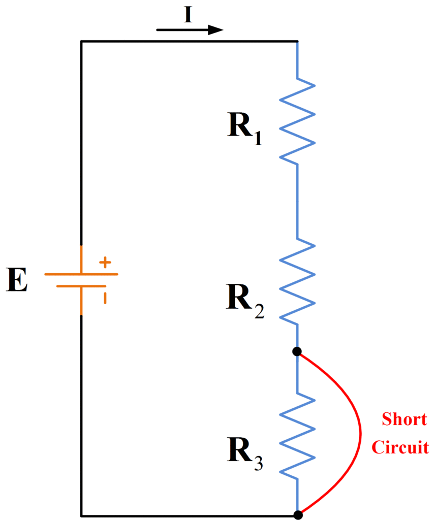
Figure 14. Circuit Diagram of Series Circuit with a Short-Circuited Connection
It is obvious that open-circuit and short-circuit seriously affect the current flow through a series resistance circuit.
- You May Also Read: Series-Parallel Circuit with Examples