The article covers the main types of variable capacitor, including rotor-stator capacitors and trimmer capacitors. It also discusses the fixed capacitor, detailing various types such as paper capacitors, plastic film capacitors, mica capacitors, ceramic capacitors, aluminum electrolytic capacitors, and tantalum electrolytic capacitors.
Variable Capacitor Types
Variable capacitors are distinguished by the fact that their capacitance can be changed. Basically, there are two most common types of such capacitors: trimmer and rotor-stator capacitors.
Rotor-Stator Capacitor
The rotor-stator type of capacitor comprises two metallic plate sets. The moving plates are attached conjointly on the shaft and make the rotor, whereas the fixed plates are linked together and constitute the stator. Capacitance is altered by turning out the shaft in a way that the rotor plates and stator plates mesh with one another while air acts as a dielectric. When the plates mesh (interlock) fully, the effective area is largest, and peak capacitance results. On the other hand, when the plates are out of contact (not meshing), the effective area decreases significantly, and minimal capacitance results. In theory, the countless variable capacitance can be actualized between the maximum and the minimum limits.
Two various types of rotor-stator capacitors are shown in Figure 1 (a) and 1 (b) with their symbols. The split-stator capacitor in Figure 1 (a) is analogous to the type of capacitor that is utilized to tune old radio receivers. The midget capacitor, shown in Figure 1(b), is employed to tune HF circuits. The scattered line linking up the symbols in Figure 1(a) suggests that capacitors are ganged up conjointly; i.e., both the capacitors’ rotors act at the same time since they are connected to a common shaft. Nevertheless, their stators are isolated from each other electrically.


Figure 1. (a) Split Stator Capacitor (b) Midget Capacitor
Trimmer Capacitor
Trimmer capacitors, as depicted in Figure 2, are small-size variable capacitors comprising two metal plates normally divided by a slim piece of mica. The capacitance is altered by changing the space between the plates by a tiny screw that pushes the plates together. Trimmer capacitors are widely employed in radio receivers to allow fine modification of the capacitance of the tuned circuit.
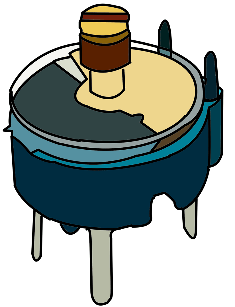
Figure 2. Trimmer Capacitor Symbol
Fixed Capacitor Types
Fixed capacitors are constructed to particular capacitances and cannot be altered. Most capacitors employed in an industry fall under this category. They are formed in different shapes and sizes, contingent on the needed capacitance, voltage rating, mounting requirements, and allowable leakage. Customarily, they are described according to the dielectric type utilized in them. The eight types of such capacitors are:
- Paper capacitors
- Plastic film extended-foil capacitors
- Mica capacitors
- Ceramic capacitors
- Monolithic ceramic chip capacitors
- Temperature-compensating ceramic capacitors
- Aluminum electrolytic capacitors
- Tantalum electrolytic capacitors
Paper Capacitor
Such types of capacitors are very cheap, hence extensively employed fixed capacitors. The dielectric (insulating material between plates) is Kraft paper, a comparatively dense and very high durability sulfate paper, between the plates of aluminum plates, rolled up collectively and instilled with resin. The whole arrangement is enclosed in a plastic or metal case in order to avoid a wet environment and contamination. Axial leads are generally got out of each end. Normal capacitances of such type run from 0.0001 to 2 μF, with 200 to 600 V voltage ratings.
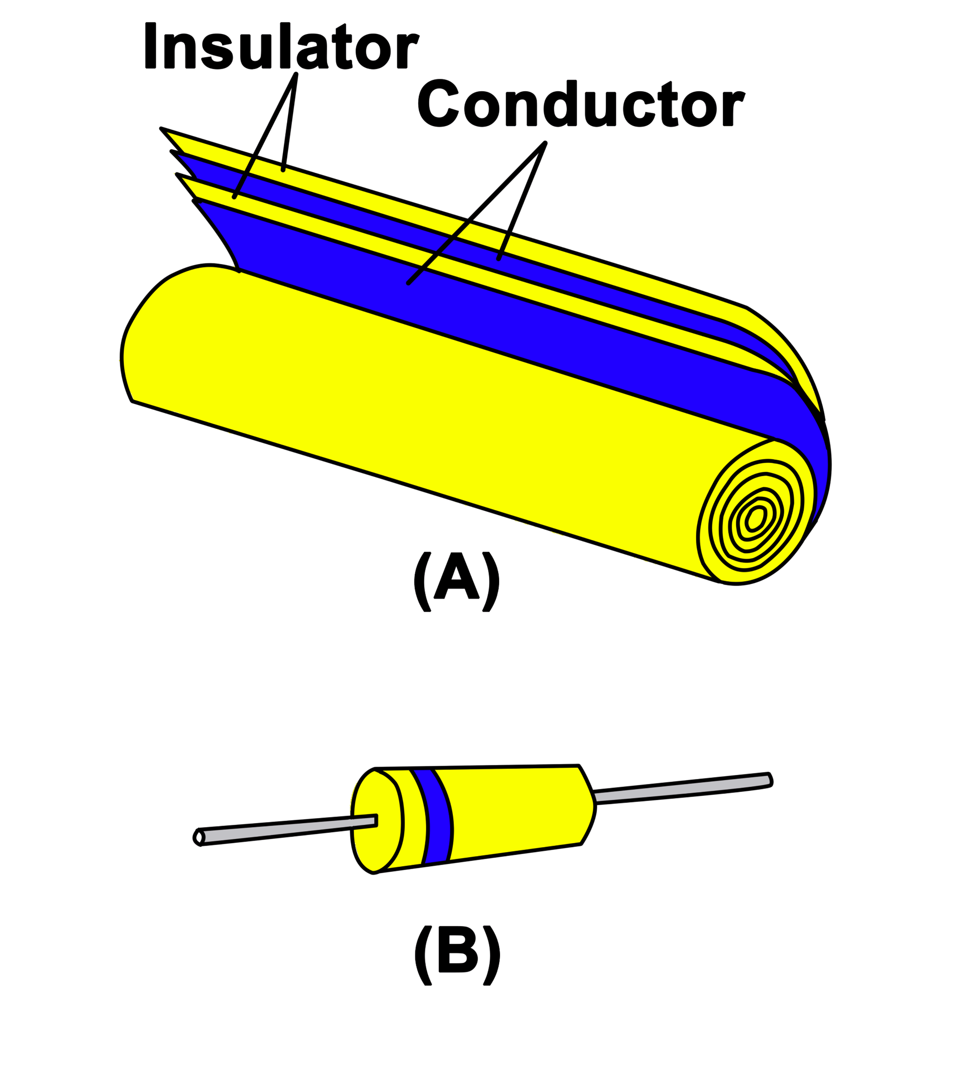
Figure 3: Paper Capacitor (a) Schematic Diagram (b) Symbol
Plastic Film Capacitor
In such types of capacitors, Plastic films like polystyrene have significantly superseded paper (dielectric) for general capacitors. Plastic is a lot denser than paper, and contaminating external particles is almost extinct. Plastic films can stand higher temperatures and are considered much more stable than paper. Structure details are demonstrated in Figure 5; such capacitor is called extended-foil capacitors. It is fundamentally not inductive because all layers of one plate are linked at one end. A variety of such capacitors are demonstrated in Figure 4, and Figure 5 exhibits the typical plastic film capacitor cross-sectional (inner structure) view.
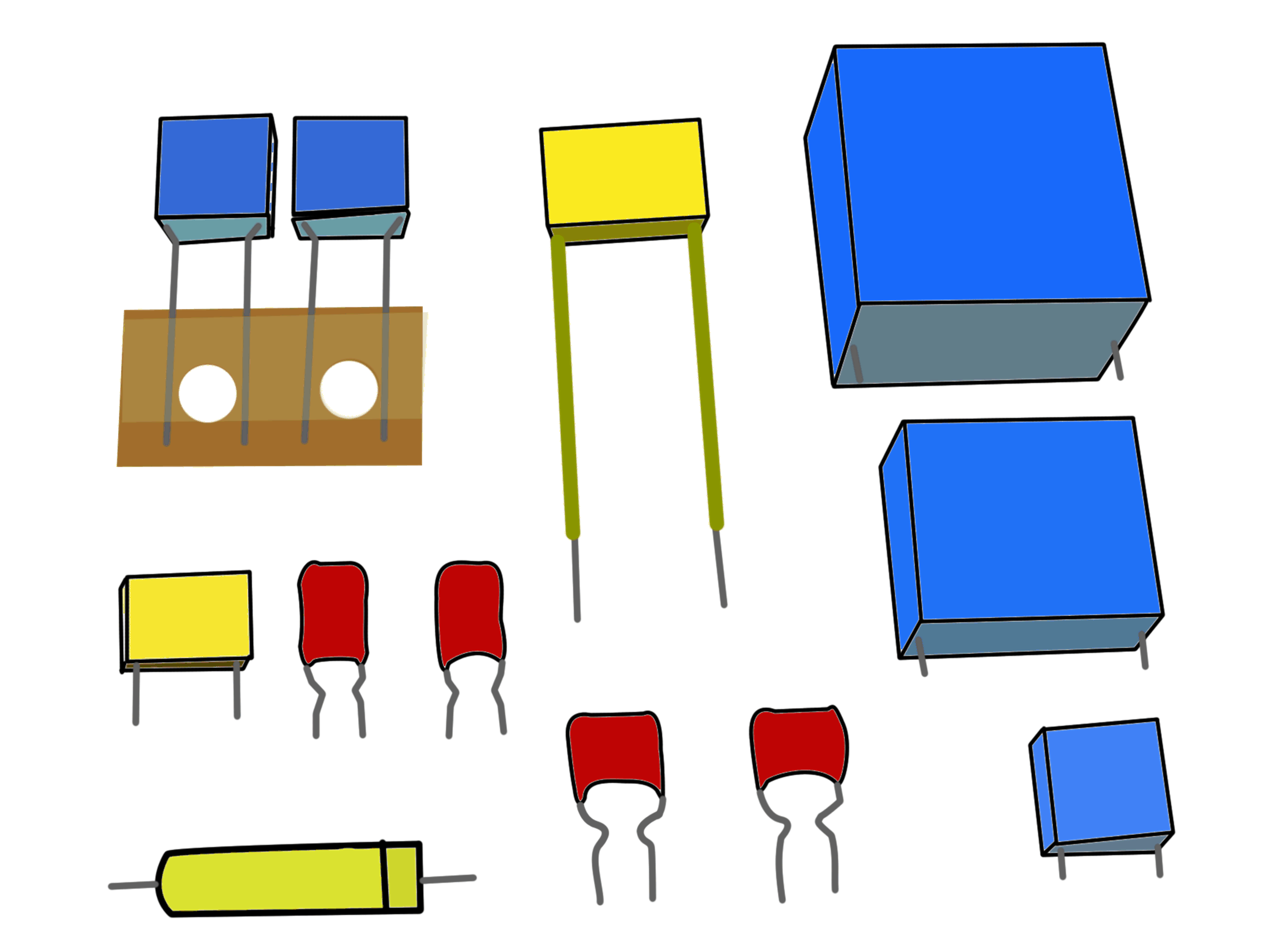
Figure 4. Plastic Film Capacitors of Different Types and Sizes
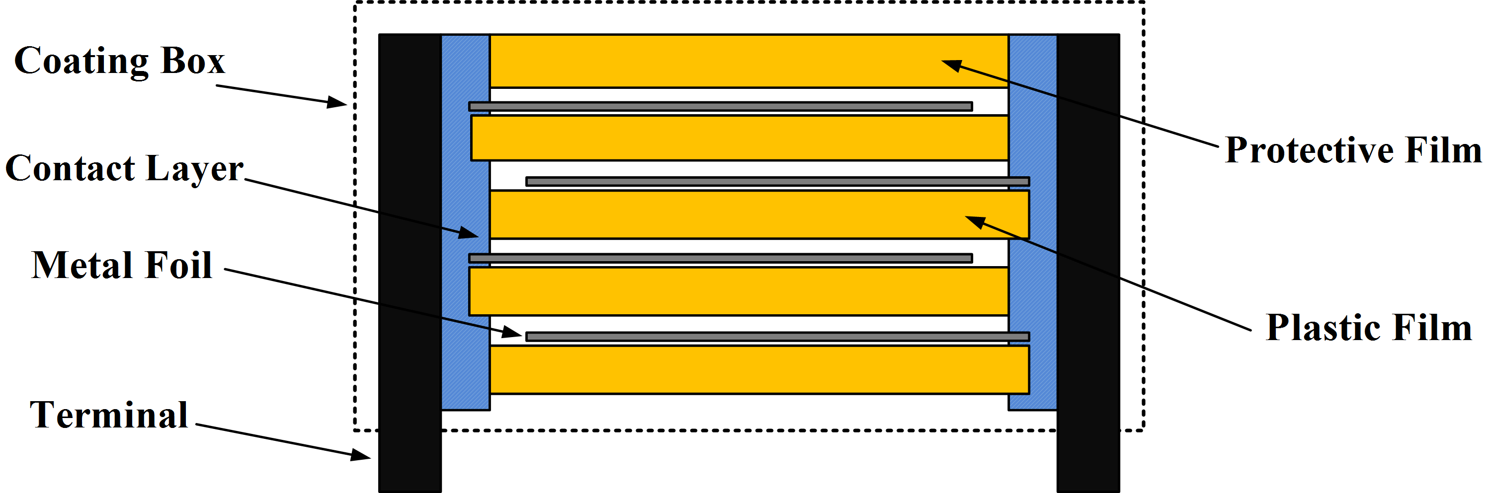
Figure 5. Cross-Sectional View of a Typical Plastic Film Capacitor
Mica Capacitor
Such types of capacitors are utilized when high voltage ratings are required. Mica is considered one of the better insulators and causes very few losses. Generally, Radio transmitters utilize such capacitors because the voltage, as well as an electric current, may go as high as 30 kV and 100 A, respectively. These capacitors are quite large physically and not common beyond 0.05 μF capacity. The construction of the Mica capacitor is demonstrated in Figure 6.

Figure 6. Mica Capacitor Construction
Silver Mica Capacitor
Another version of Mica capacitors is known as Silver-Mica capacitors, as depicted in the following Figure 7. In such types of capacitors, a very thin silver layer is deposited on the mica surface, and the resultant capacitor possesses very superior stability and tolerance. Such units are primarily utilized for temperature compensation in RF circuits due to their inevitable, linear temperature-capacitance fluctuations.
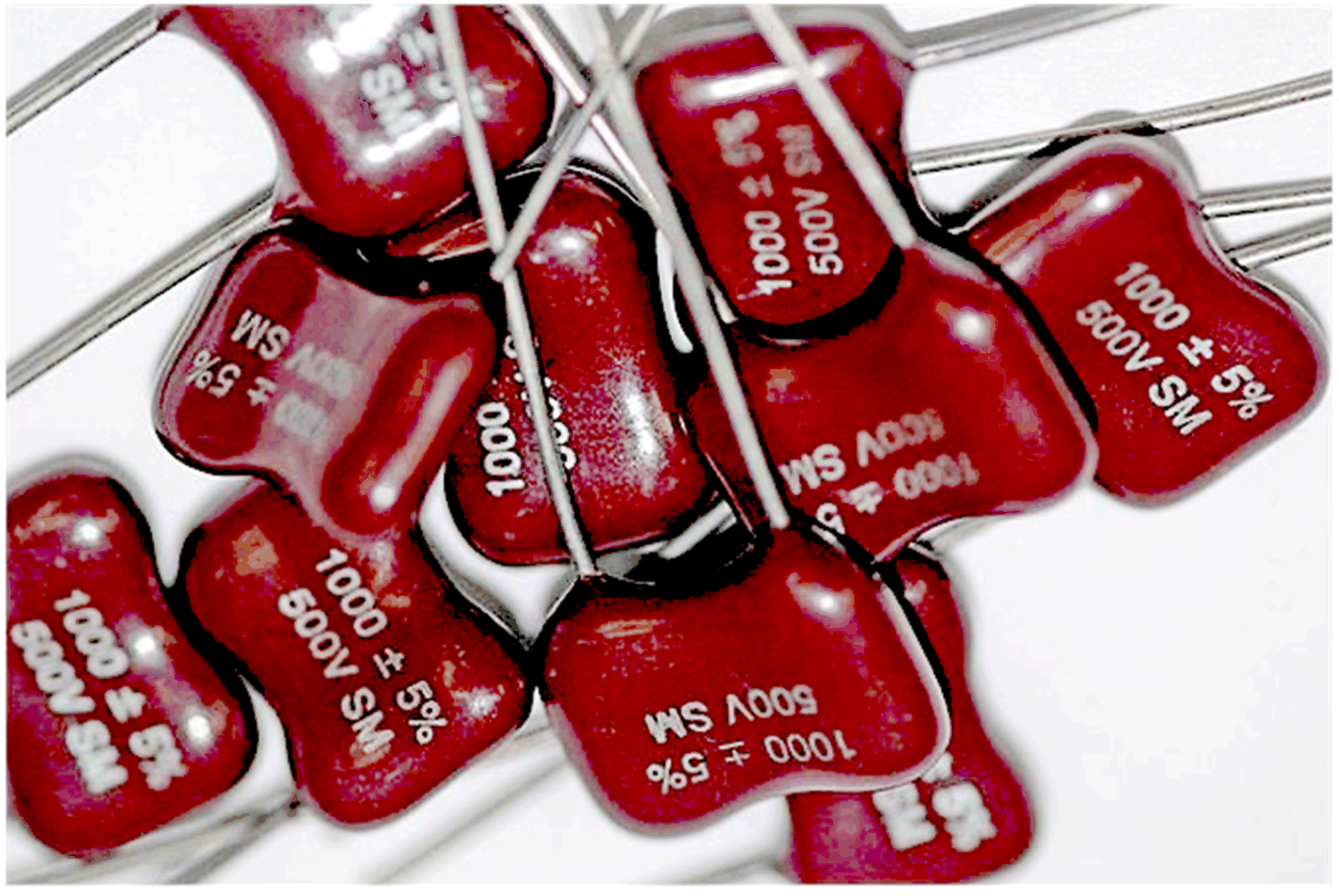
Figure 7. Typical Silver-Mica Capacitor
Ceramic Capacitor
Such type of capacitors comprises a ceramic-made disc with silver electrodes linked to each flat surface. Leads are attached to these electrodes to allow connection to the unit. Figure 8 exhibits the ceramic disc capacitor structure. These types of capacitors are utilized in certain applications ranging from low to very high frequency through 1000 Mega-Hz. Dielectric materials are formed from barium and strontium titanates mixtures, combined with rare earth and other additives in order to enhance electric characteristics.
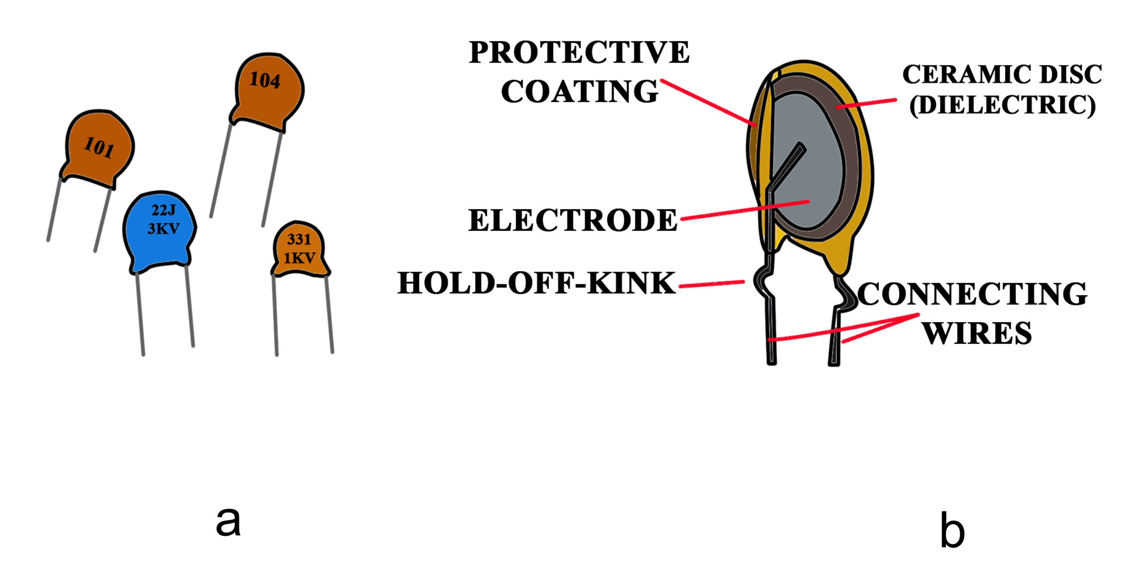
Figure 8. (a) Ceramic Disc Capacitor Symbol (b) Construction of a ceramic disc capacitor
Monolithic Ceramic Chip Capacitors
Monolithic ceramic chip capacitors have become very popular because they save space and achieve capacitance values that are difficult to attain by either thick or thin film capacitors. Capacitance values in excess of 100,000 pF are easily achievable with ceramic multilayer chips that measure 100 by 180 mils and less. These capacitors are used extensively in all kinds of analog and digital integrated circuits. In off-chip bypass applications, multilayer chips are used because they have higher volumetric efficiency than ceramic discs. Also, they can be obtained in single and dual inline configurations.
Multilayer construction techniques produce a very high ratio of capacitance to volume with a minimum of self-inductance. The capacitor sections are made by alternately depositing very thin layers of ceramic dielectric materials and metallic electrodes until the desired capacitance is achieved. The resultant capacitors are then fired into an all but indestructible solid block. Construction details of a typical multiple-layer ceramic capacitor are shown in Figure 9.

Figure 9. (a) Multilayer Ceramic Capacitor Symbol (b) Detailed construction of a Multilayer Ceramic Capacitor
Temperature Compensating Ceramic Capacitors
Temperature-compensating ceramic capacitors exhibit controlled, predictable changes in capacitance with temperature changes. If the capacitance value increases with an increase in temperature, the capacitor has a positive temperature coefficient and is classified with the letter P. This type of capacitor is rarely used.
Ceramic capacitors that remain stable with changes in temperature are called NP0 (negative-positive-zero) capacitors. These capacitors are even more stable than silver-mica capacitors. They are used in many kinds of receivers and generally have values between 1 pF and 0.033 μF.
Ceramic capacitors that have a negative temperature coefficient are widely used in TV and quality radio receivers to stabilize tuned circuits that otherwise would change the frequency with any change in temperature. Because a radio frequency coil or an intermediate-frequency transformer has a positive temperature coefficient of inductance, its inductance will increase with any increase in temperature, and the tuned frequency will therefore decrease. If the tuned circuit capacitance change is selected to be exactly equal but opposite to the inductance change, their product will remain constant, and the resonant frequency will not vary with temperature changes.
Aluminum Electrolytic Capacitors
Such types of capacitors are utilized when a large capacitance is required, and leakage current is not an important factor. The capacities of such units range from a few microfarads to thousands of farads. Typically, they are not rated beyond 450 V in values equal to several hundred microfarads. The voltage ratings of capacitors decrease as the capacity goes up since thinner dielectrics are utilized with bigger capacities, and consequently, inferior voltage ratings result.
In its most common form, the construction of electrolytic capacitors is just like the paper capacitor. The positive terminal of the unit is formed of aluminum foil, and one side is covered up with a very thin oxide layer, which is actually the dielectric. In link with this layer, there is an electrolyte in the paste form, which functions as the capacitor negative plate. The second aluminum foil strip is laid against the paste to make an electric contact. It is this association that becomes the capacitor-negative terminal. In such capacitor types, bigger capacities are achievable since the metal foil (aluminum foil) is chemically engraved to bring out the grain structure of the metal, which actually steps up the effective area exposed to the electrolyte.
Such types of capacitors are polarized. In case the positive plate is unexpectedly linked up to a negative terminal of the voltage source, the thin oxide layer of dielectric will vanish, and the capacitor will act as a short. Since they are polarity-sensitive, electrolytic types of capacitors are generally restrained to utilize in DC circuits.
There is some leakage current with electrolytic. Usually, it increases with age, especially if the capacitor has not been in use. The amount of leakage is a fair indication of quality, with larger units having more than small ones. Figure 10 shows several types and styles of electrolytic capacitors, and Figure 11 shows the schematic structure. Figure 12 shows the construction details of a typical aluminum electrolytic capacitor with a non-solid electrolyte.

Figure 10. Aluminum Electrolytic Capacitors of Different Types and Sizes

Figure 11. Schematic representation of an aluminum electrolytic capacitor with non-solid electrolyte

Figure 12. Construction of an aluminum electrolytic capacitor with non-solid electrolyte
Tantalum Electrolytic Capacitor
Such types of capacitors are highly stable electrolytic capacitors recognized. Pure tantalum, which is a rare earth metal, is silver gray. The metal was named tantalum since it is so “tantalizingly” unreactive. It stays unchanged when absorbed in most acids. The element is highly resistant to attack by most chemicals under 350 oF.
A very thin film of tantalum oxide is exceedingly stable and sustains superior dielectric characteristics. Accordingly, tantalum is perfect for utilization in electrolytic capacitors. Tantalum electrolytic capacitors are perfect to use where reliability and long service life are of extreme concern.
There are two conducting surfaces in a tantalum electrolytic capacitor, which are detached from an insulation material. This insulating or dielectric material is tantalum pentoxide, and it is commonly utilized in all types of tantalum electrolytic capacitors. Tantalum pentoxide is such an effective compound that possesses very superior dielectric strength as well as dielectric constant. A thin film of this material is deposited on the tantalum capacitor electrodes by an electrolytic method. Tantalum pentoxide possesses a dielectric constant of 26, which is about three times bigger than aluminum oxide. This high dielectric constant and the fact that exceedingly thin films can be deposited by the electrolytic method indicate that the tantalum capacitors are very effective in terms of the number of microfarads available per unit volume. Foil tantalum-type capacitors are approximately one-third the size of aluminum electrolytic capacitors. Figure 13 shows tantalum capacitors in various shapes and sizes according to their ratings.

Figure 13. Tantalum Capacitors in Various Shapes and Sizes
In solid electrolyte-type tantalum capacitors, a dry substance known as manganese dioxide serves as an electrolyte. This solid and conductive substance makes the cathode (negatively charged) capacitor plate.
Foil Tantalum Capacitor
Foil tantalum capacitors are constructed by rolling up two thin foil strips, detached by a paper that is concentrated (saturated) with electrolyte, into a convolute roll. The tantalum foil (which acts as an anode) is chemically inscribed in order to step-up its effective surface area, therefore offering more capacitance in an available volume. This etching process is followed by anodization in a chemical solution under direct voltage application. This anodization process, in turn, develops the dielectric tantalum pentoxide film on the foil surface. Foil tantalum capacitors are broadly constructed for operation over the temperature range of -55 oC to +125 oC and are found principally in industrial and military electronic equipment.
Sintered-anode, wet electrolyte-type tantalum capacitors and sintered-anode, solid electrolyte-type capacitors have one thing in common; a pellet of sintered tantalum powder to which a lead has been bonded. This anode possesses a tremendous surface area because of the way it is constructed. Tantalum powder of an appropriate fineness, sometimes amalgamated with binding agents, is machine-pressed into pellets. The next step is a sintering operation in which impurities, binders, and contamination are evaporated, and the tantalum particles are sintered (welded) into a porous mass with a very big internal surface area. Following the sintering and before the development of the dielectric (insulating material) film on the pellet, a tantalum lead wire is linked by welding the wire to the pellet. Figure 14 shows the construction of the typical tantalum electrolytic capacitor with the solid electrolyte.

Figure 14. Construction of a typical tantalum electrolytic capacitor with solid electrolyte and labeled diagram
An electrochemical process on the surface areas of the combined tantalum particles establishes a tantalum pentoxide film. Given adequate time and current is accessible, the oxide will get to a thickness settled by the applied voltage. The pellet is then introduced into a tantalum or silver can that carries an electrolytic solution. Most liquid electrolytes are gelled in order to avoid the independent movement of the solution inside the container and to hold the electrolyte in close contact with the capacitor cathode. An appropriate end seal organization prohibits the loss of the electrolyte. A cutaway view of a sintered anode tantalum capacitor is demonstrated in Figure 15.

Figure 15. Cross-sectional view of a sintered anode tantalum electrolytic capacitor
Capacitor Types Key Takeaways
Variable capacitors play a crucial role in a wide range of electronic applications due to their ability to adjust capacitance. From fine-tuning radio receivers to stabilizing circuits in high-voltage environments, these capacitors offer versatility and reliability. Additionally, fixed capacitors provide essential capacitance values for specific applications, each type tailored to meet diverse requirements such as voltage rating, mounting needs, and environmental conditions. Understanding the characteristics and applications of variable and fixed capacitors is essential for designing and maintaining electronic systems across various industries, ensuring optimal performance and efficiency.