This guide covers Parallel RC Circuit Analysis, Phasor Diagram, Impedance & Power Triangle, and several solved examples along with the review questions answers.
This guide covers The combination of a resistor and capacitor connected in parallel to an AC source, as illustrated in Figure 1, is called a parallel RC circuit.
The conditions that exist in RC parallel circuits and the methods used for solving them are quite similar to those used for RL parallel circuits. The voltage is the same value across each parallel branch and provides the basis for expressing any phase differences. The principle difference is one of phase relationship.
In a pure capacitor the current leads the voltage by 90 degrees, while in a pure inductor the current lags the voltage by 90 degrees.
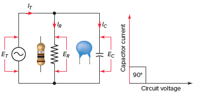
Figure 1 Parallel RC circuit.
Parallel RC Circuit Phasor Diagram
The relationship between the voltage and currents in a parallel RC circuit is illustrated in the vector (phasor) diagram of Figure 2 and summarized as follows:
- The reference vector is labeled E and represents the voltage in the circuit, which is common to all elements.
- Since the current through the resistor is in phase with the voltage across it, IR (8 A) is shown superimposed on the voltage vector.
- The capacitor current IC (12 A) leads the voltage by 90 degrees and is positioned in an upward direction, leading the voltage vector by 90 degrees.
- The vector addition of IR and IC gives a resultant that represents the total (IT) or line current (14.4 A).
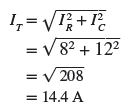
- The angle theta (θ) represents the phase between the applied line voltage and current.
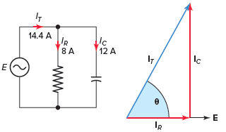
Figure 2 Parallel RC circuit vector (phasor) diagram.
In a parallel RC circuit, the line current leads the applied voltage by some phase angle less than 90 degrees but greater than 0 degrees. The exact angle depends on whether the capacitive current or resistive current is greater. If there is more capacitive current, the angle will be closer to 90 degrees, while if the resistive current is greater, the angle is closer to 0 degrees.
The value of the phase angle can be calculated from the values of the two branch currents using the following equation:

Current in Parallel RC Circuit Example 1
For the parallel RC circuit shown in Figure 3, determine:
- Current flow through the resistor.
- Current flow through the capacitor.
- Total line current.
- The phase angle between the voltage and total current flow.
- Express all currents in polar notation.
- Use a calculator to convert all currents to rectangular notation.
Figure 3 Circuit for example 1.
Solution:
\[\text{a}\text{. }{{\text{I}}_{\text{R}}}\text{=}\frac{\text{E}}{\text{R}}\text{=}\frac{\text{120V}}{\text{10 }\!\!\Omega\!\!\text{ }}\text{=12A}\]
\[\text{b}\text{. }{{\text{I}}_{\text{C}}}\text{=}\frac{\text{E}}{{{\text{X}}_{\text{C}}}}\text{=}\frac{\text{120V}}{\text{20 }\!\!\Omega\!\!\text{ }}\text{=6A}\]
\[\text{c}\text{. }{{\text{I}}_{\text{T}}}\text{=}\sqrt{\text{I}_{\text{R}}^{\text{2}}\text{+I}_{\text{C}}^{\text{2}}}\text{=}\sqrt{{{12}^{\text{2}}}\text{+}{{\text{6}}^{\text{2}}}}\text{=13}\text{.4A}\]
\[d.\theta ={{\tan }^{-1}}\left( \frac{{{I}_{C}}}{{{I}_{R}}} \right)={{\tan }^{-1}}\left( \frac{6}{12} \right)={{26.6}^{o}}\]
\[\begin{matrix}\text{e}\text{. }{{\text{I}}_{\text{T}}}\text{=13}\text{.4}\angle {{26.6}^{o}}^{\text{o}} & {{\text{I}}_{\text{R}}}\text{=12}\angle {{\text{0}}^{\text{o}}} & {{\text{I}}_{\text{C}}}\text{=6}\angle \text{9}{{\text{0}}^{\text{o}}} \\\end{matrix}\]
\[\text{f}\text{.}\begin{matrix}\text{ }{{\text{I}}_{\text{T}}}\text{=12+j6} & {{\text{I}}_{\text{R}}}\text{=12+j0} & {{\text{I}}_{\text{C}}}\text{=0+j6} \\\end{matrix}\]
Parallel RC Circuit Impedance
The impedance (Z) of a parallel RC circuit is similar to that of a parallel RL circuit and is summarized as follows:
- Impedance can be calculated directly from the resistance and capacitive reactance values using the equation
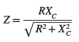
- Impedance can be calculated using the Ohm’s law equation
![]()
- The impedance of a parallel RC circuit is always less than the resistance or capacitive reactance of the individual branches.
Impedance in Parallel RC Circuit Example 2
For the parallel RC circuit shown in Figure 4 determine the:
- Current flow through the resistor (IR).
- Current flow through the capacitor (IC).
- The total line current (IT).
- Impedance (Z).
- Phase angle between the voltage and total current flow.
- If the circuit is more resistive or capacitive.
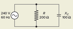
Figure 4 Circuit for example 2.
Solution:
\[\text{a}\text{. }{{\text{I}}_{\text{R}}}\text{=}\frac{\text{E}}{\text{R}}\text{=}\frac{\text{240V}}{\text{200 }\!\!\Omega\!\!\text{ }}\text{=1}\text{.2A}\]
\[\text{b}\text{. }{{\text{I}}_{\text{C}}}\text{=}\frac{\text{E}}{{{\text{X}}_{\text{C}}}}\text{=}\frac{\text{240V}}{\text{100 }\!\!\Omega\!\!\text{ }}\text{=2}\text{.4A}\]
\[\text{c}\text{. }{{\text{I}}_{\text{T}}}\text{=}\sqrt{\text{I}_{\text{R}}^{\text{2}}\text{+I}_{\text{C}}^{\text{2}}}\text{=}\sqrt{\text{1}\text{.}{{\text{2}}^{\text{2}}}\text{+2}\text{.4}{{\text{0}}^{\text{2}}}}\text{=2}\text{.68A}\]
\[\text{d}\text{. Z=}\frac{\text{E}}{{{\text{I}}_{\text{T}}}}\text{=}\frac{\text{240V}}{\text{2}\text{.68A}}\text{=89}\text{.6 }\!\!\Omega\!\!\text{ }\]
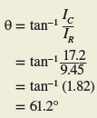
\[d.\theta ={{\tan }^{-1}}\left( \frac{{{I}_{C}}}{{{I}_{R}}} \right)={{\tan }^{-1}}\left( \frac{2.4}{1.2} \right)={{63.4}^{o}}\]
f. The circuit is more capacitive in nature because the capacitive current is greater than the resistive current.
Power in Parallel RC Circuit
The power components for a parallel RC circuit are illustrated in Figure 5. The formulas that apply are the same as that of a parallel RL circuit:
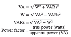
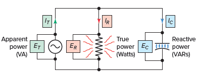
Figure 5 Power components of a RC parallel circuit.
Parallel RC Circuit Power Factor
The power factor of a parallel RC circuit is always leading. Any time the branch resistance increases, less current flows through it and the circuit becomes more capacitive, resulting in a lower power factor. The reverse is true if the resistance decreases.
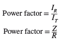
With current or resistance and impedance values, the power factor can be determined as follows:
Parallel RC Circuit Calculations Example 3
For the parallel RC circuit shown in Figure 6, determine the:
- Capacitive reactance of the capacitor (XC).
- Current flow through the capacitor (IC).
- Reactive power of the capacitor (VARs).
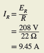
- Current flow through the resistor (IR).
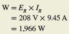
- True power (W).
- Total line current flow (IT).
- Circuit impedance (Z).
- Apparent power (VA).
- Power factor (PF).
- Circuit phase angle θ.
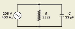
Figure 6 Circuit for example 3.
Solution:
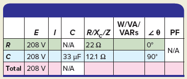
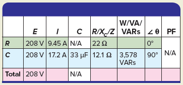
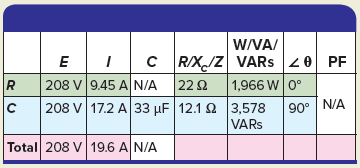
- Step 1. Make a table and record all known values.
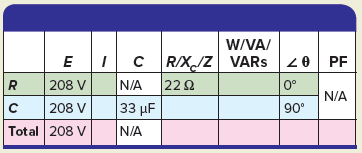
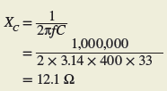
- Step 2. Calculate the capacitive reactance of the capacitor and enter the value in the table.
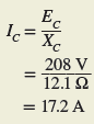
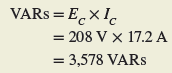
- Step 3. Calculate the current flow of the capacitor and enter the value in the table.
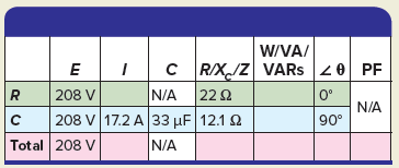
- Step 4. Calculate the reactive power of the capacitor and enter the value in the table.

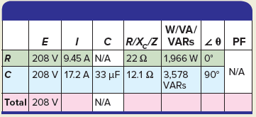
- Step 5. Calculate the current flow through the resistor and enter the value in the table.
- Step 6. Calculate the true power and enter the value in the table.
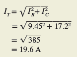
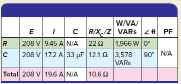
- Step 7. Calculate the total line current and enter the value in the table.
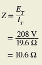
- Step 8. Calculate the impedance and enter the value in the table.
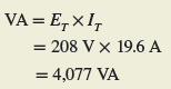
- Step 9. Calculate the apparent power and enter the value in the table.
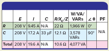
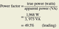
- Step 10. Calculate the power factor and enter the value in the table.
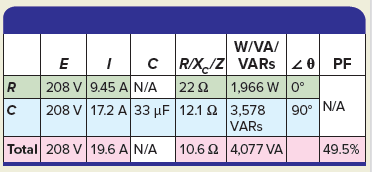
- Step 11. Calculate the circuit phase angle θ and enter the value in the table.
Review Questions
- What is the main difference between a parallel RL and RC circuit?
- Assume the resistance of the resistive component of a parallel RC circuit is increased. What effect, if any, will this have on the phase angle of the circuit?
- A parallel RC circuit is connected to a 100-volt, 60-Hz source. The current flow through the resistor is measured and found to be 10 amps. The current flow through the capacitor is measured and found to be 10 amps. Determine:
- Line current (IT).
- Impedance (Z).
- True power (W).
- Reactive power (VARs).
- Apparent power (VA).
- PF percentage.
- For the circuit shown in Figure 7, determine:

Figure 7 Circuit for review question 4.
-
- The amount of current flow through the resistor.
- The capacitive reactance of the capacitor.
- The amount of current flow through the capacitor.
- The line current.
- Apparent power.
- PF percentage.
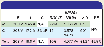
5. Complete a table for all given and unknown quantities for the parallel RC circuit shown in Figure 8.
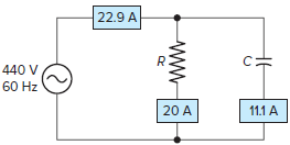
Figure 8 Circuit for review question 5.
Review Questions – Answers
- The principle difference is one of phase relationship. In a pure capacitor the current leads the voltage by 90°, while in a pure inductor the current lags the voltage by 90°.
- If the resistance of an RC circuit is increased, the resistive current will be decreased and the circuit will become more capacitive and the phase angle will become larger.
- (a) 14.14 A, (b) 7.07 Ω, (c) 1000 W, (d) 1000 VARs, (e) 1414 VA, (f) 70.7% leading
- (a) 80 A, (b) 1.77 Ω, (c) 67.8 A, (d) 105 A, (e) 12600 VA, (f) 76.2% leading
| E | I | C | R /XC /Z | W/VA/VARs | PF | ||
| R | 440 V | 20 A | N/A | 22 Ω | 8800 W | 0 | |
| C | 440 V | 11.1 A | 67 uF | 39.6 Ω | 4884 VARs | 90 | |
| Total | 440 V | 22.9 A | N/A | 19.2 Ω | 10076 VA | 29.2 | 87.3 % |