This guide covers electrical tests (continuity test, insulation to earth test, and insulation test between windings) and visual tests carried out for electric motor maintenance.
Electrical Tests for Three-Phase Motor Windings
The tests applicable to an electric motor are either electrical or visual—usually both. Electrical tests are possibly the easiest to carry out (assuming that the equipment is available) because it often means there is no need to dismantle the motor; the testing can be done at the terminal box. Subject to the results of the electrical test it may then be necessary to dismantle the motor.
- Continuity Test
Low voltage sources such as multi-meters are suitable for continuity testing. The regular multimeter is of the series ohmmeter type and care must be exercised in taking any resistance readings as absolute readings, particularly at very low values. If a winding is supposed to read 1 Ω, then a meter reading of say 0.7 Ω is pointless, since the accuracy of the meter itself might be in question. All it will establish is that there is some resistance and some form of electrical continuity between the two leads being checked.
Without some knowledge of the electric motor circuit it cannot be established whether the correct part of the circuit is actually being tested. For example, if a three-phase motor connected in delta configuration is being tested, an ohmmeter would give a reading across any pair of terminals even if one phase winding was an open circuit.
In Figure 1 overleaf phase winding A is open circuit, yet a reading can be obtained between L1 and L2 (phase B), also between L2 and L3 (phase C), and between L1 and L3 (phases B and C in series). If the electric motor is large, the winding resistance is low and it might be difficult for ohmmeters to detect the difference in readings. Then it might be necessary to disconnect the delta bridges and check the phases individually.
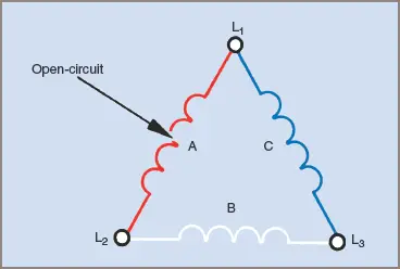
Figure 1 Delta-connected electric motor with one phase open-circuited
A similar situation occurs with single-phase electric motors. When testing the motor it must be known whether the two windings are in parallel, whether there is a capacitor in the circuit, if the motor has a starting switch and if it is operational.
- Insulation-To-Earth Test
An insulation-to-earth test must be made with instruments of the correct voltage. A 415 V circuit, for example, cannot be tested satisfactorily with a 3 V ohmmeter. Similarly a small-town local supply with an exciter rated at 24 V should not be tested with an insulation tester of 500 V.
Again there should be some prior knowledge of the circuit of the electric motor. Each phase or winding should be tested separately and the results compared. One phase with a reading considerably different to the other two could indicate a problem.
- Insulation Test between Windings
For an insulation test between windings, the windings should be disconnected from each other and the supply source to enable a meaningful test. Again a suitable test voltage should be used and the relative readings compared for variation. A low reading between two phases is an indication of a problem.
Visual Inspection
If after electrical testing a further check is required, the electric motor is usually dismantled for a visual inspection. With very large machines a limited visual inspection is possible by removing covers and looking inside without dismantling the complete machine. In the greater proportion of instances burnt-out motors have a characteristic smell that is quite easy to detect.
Probably most obvious is the sign of heat within the windings and associated with the burnt smell. Insulation can be charred and windings can consist of bar copper wire with all covering burnt off. The burning smell is not an infallible indication, however, because the fault can trip the supply before the burning becomes appreciable.
- You May Also Read: Electric Motor Parts and Construction
Non-electrical tests indicating burnt insulation include pressing the winding with the hands and listening for a crackling noise (a winding in good condition should make no noise), rubbing the bindings with the fingers to see if they crumble and, on larger electric motors, tapping the windings lightly with a small hammer (a faulty coil group sometimes gives a flatter sound than the rest of the windings, giving a lead to a fault).
Where windings have short-circuited to earth, small holes in the windings with associated copper globules, can occasionally be seen. With lighter-colored enamels and varnishes faulty turns and coils can be clearly seen as very much darker than the rest of the windings.
Specialized Test Equipment
There are times when the above checks do not give a definite answer as to the condition of the windings. If an electric motor is faulty in operation and passes the above tests, then further testing is necessary. One popular method involves using the windings as the secondary of a transformer with a piece of equipment called a ‘growler’—a name given for the noise made when it is in operation.
One type is designed for the testing of armature windings and has a vee-shaped gap in which to place the armature. When alternating current is applied to the growler an alternating voltage is induced in the armature windings. The induced voltages on opposite sides of the armature are equal and opposing, so no circulating current flows. If there is a short-circuit in the windings, this balance is upset and a circulating current flows.
The faulty coil can be detected by a light-gauge strip of steel held against the armature—it vibrates when laid along the slot holding the faulty coil. One variation of this is where the vee-shaped gap is rounded to sit inside the stator of an electric motor and a similar operating procedure is followed.
Some models of growler have the vee on one side and the rounded section on the other. Another piece of test equipment, the Prufex, is sometimes used with motor stators. It is plugged into an AC supply and moved around inside the stator. If a short-circuit exists in the stator windings, the circulating currents upset the magnetic field of the tester and a light flashes, indicating the location of the fault.
Dismantling Three-Phase Electric Motor
When dismantling an electric motor, the main aim after any inspection or repairs is to reassemble it in the original form. To make it easier than just relying on memory or previous experience, it is a common practice to mark the end-shields and other pieces in some way.
Probably the most common method is to use a center punch and make adjacent punch marks on matching surfaces. They should not be placed on machined surfaces. Some technicians prefer to use a cold chisel and make one mark across two surfaces, the intention being to be able to reassemble the motor more accurately. In either case only a light mark is needed so long as it can be used on reassembly.
It is not recommended that large deep marks be made because of the possibility of damage to the casing. Called ‘witness marks’ by some, it is nevertheless good practice and is used extensively by experienced technicians. For example, an end-shield could be marked with a single center-punch mark on both the end-shield and the motor frame. It is quite customary to place these marks at the top of the motor where they can be easily seen. The opposite end-shield could then be marked with two closely spaced punch marks. A similar method could be used on the bearing covers.
If in a position to do so, an experienced operator will often keep components of sub-assemblies separate from other sub-assemblies as they are removed. It is bad practice to put all components in one container and then have to attempt to sort them out when required for reassembly.
Withdrawal of the rotor from the stator calls for some care to ensure that no damage is caused by the worker to either the rotor or the stator and its windings. A mechanical and electrical examination of the electric motor can then take place.
Matching punch marks when rebuilding is a quick and accurate method of ensuring that the motor is assembled in its prescribed condition and manner. It also ensures that the electric motor shaft is protruding from the right end and the terminal block and housing is in the correct position.
Bearings should be checked for wear and re-greased on assembly with just the right amount of correct-grade grease.
Electric Motor Maintenance Key Takeaways
The electrical and visual tests outlined in this guide—continuity testing, insulation-to-earth testing, insulation testing between windings, and visual inspections—play a critical role in maintaining the health and efficiency of electric motors. These diagnostic methods are essential for identifying issues early, preventing unexpected motor failures, and ensuring operational safety. In practical applications, such as in industrial machinery, HVAC systems, and manufacturing plants, the reliable performance of electric motors is vital. Regular testing not only minimizes downtime and repair costs but also extends the life of the equipment, making these procedures indispensable for technicians and maintenance teams working with three-phase motors.