The article covers various methods for measuring electrical resistance, including low resistance measurement using voltmeters and ammeters, ohmmeter functionality and calibration, high resistance measurement techniques using voltmeters, and precision measurement using the Wheatstone bridge. It explains the principles behind each method, factors affecting accuracy, and provides practical examples for calculating resistance values.
Low Resistance Measurement
We can determine an unknown resistance in Figure 1 by applying Ohm’s law to the readings obtained from the voltmeter and ammeter. This method requires that the unknown resistance is connected into a special circuit with two separate meters. This method is useful for measuring very low resistances, such as those of motors, and for measuring the resistance of a component while it carries its normal operating current.
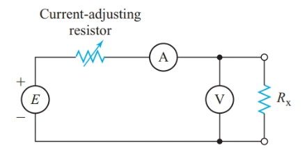
Figure 1 Measuring resistance with a voltmeter and an ammeter
With the voltmeter connected as shown in Figure 1, the ammeter indicates the sum of the currents through Rx and the voltmeter. Thus, the V/I ratio calculated from the meter readings equals the equivalent resistance of the two parallel branches. This ratio is less than the actual value of Rx unless the voltmeter current is negligible compared to the current through Rx.
We can check for voltmeter loading by watching the ammeter reading as we disconnect the voltmeter. If there is any noticeable decrease in the current, we then connect the voltmeter on the source side of the ammeter. The ammeter now reads only the current through Rx while the voltmeter now shows the sum of the voltage drops across the ammeter and Rx.
However, if Rx is large enough to show a noticeable voltmeter loading effect, the voltage drop across the ammeter is insignificant compared to Vx and we can ignore the ammeter loading effect.
Ohmmeter
For quick checks of circuit resistance, we can use an ohmmeter, a meter designed to measure resistance directly. The simple ohmmeter showed in Figure 2(a) consists of a 1.0-mA movement, a 4.5-V battery, and a resistance that passes a 1.0-mA current when we short-circuit the ohmmeter terminals. A portion of the total resistance is adjustable so that we can calibrate the meter to read exactly full scale when we connect the two test leads together. In this example, the total resistance, including the meter movement, is
\[{{R}_{T}}=\frac{E}{I}=\frac{4.5V}{1.0mA}=4.5k\Omega \]
As shown in Figure 2(b), the scale of an ohmmeter is nonlinear. The nonlinear scale makes low resistances easier to read accurately, but high resistances are crammed together at the left end of the scale. For circuit testing where we need a high-range ohmmeter, we could use a 50-μA movement rather than a 1.0-mA movement. With a 50-μA movement, the total internal resistance of the ohmmeter in Figure 2(a) is
\[{{R}_{T}}=\frac{E}{I}=\frac{4.5V}{50\mu A}=90k\Omega \]
The center-scale reading of the meter will also be 90 kΩ.
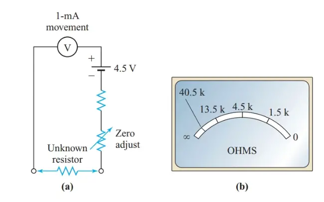
Figure 2 Resistance measurement using Ohmmeter
Example 1
Determine the resistance values that should be marked at full scale, center scale, one-quarter of full scale, and one-tenth of full scale for the ohmmeter in Figure 2.
Solution
As we have already noted, the total internal resistance of the ohmmeter is adjusted so that the meter reads exactly full scale when the test leads are short-circuited. Therefore, the end mark on the scale represents 0 Ω.
When the meter reads the half scale, the current is 0.5 mA and the total resistance in the series loop is double the total ohmmeter resistance. Therefore, a center-scale reading represents
\[{{R}_{X}}={{R}_{M}}=\frac{E}{I}=\frac{4.5V}{1.0mA}=4.5k\Omega \]
For one-quarter of full scale, the current is 0.25 mA. Then, the total resistance in the loop is
\[{{R}_{T}}=\frac{E}{I}=\frac{4.5V}{0.25mA}=18k\Omega \]
And
\[{{R}_{X}}=18k\Omega -4.5k\Omega =13.5k\Omega \]
Similarly, one-tenth of the full scale represents
\[{{R}_{X}}=\frac{E}{I}=\frac{4.5V}{0.10mA}-4.5k\Omega =40.5k\Omega \]
These examples demonstrate that the resistance represented by a center-scale reading is inversely proportional to the full-scale current for the meter. Therefore, we can convert the basic ohmmeter into a low range ohmmeter by placing a shunt across the moving coil, as shown in Figure 3.
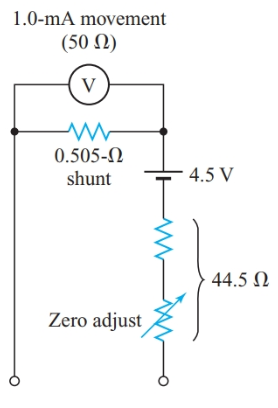
Figure 3 Low-range ohmmeter
Example 2
Using a 1.0-mA movement with an internal resistance of 50 Ω and a 4.5-V battery, design an ohmmeter that reads 45 Ω at center scale.
Solution
For a center-scale reading, Rx = RM, so the total internal resistance of the ohmmeter is 45 Ω. Therefore, full-scale current is
\[I=\frac{E}{R}=\frac{4.5V}{45\Omega }=0.10A\]
Since the meter movement passes 1.0 mA at full scale, the shunt current must be 99 mA. The shunt resistance is
\[{{R}_{sh}}=\frac{1mA}{99mA}\times 50\Omega =0.505\Omega \]
The equivalent resistance of the meter movement and shunt in parallel is
\[{{\operatorname{R}}_{eq}}=\frac{50\times 0.505}{50+0.505}=0.500\Omega \]
Therefore, the total resistance of the series resistor and the “ohms adjust” rheostat is
\[{{R}_{S}}=45-0.5=44.5\Omega \]
As with a voltmeter, we can readily connect an ohmmeter across a portion of a circuit. However, we must make sure that the circuit being measured is switched off. Current from sources in the circuit can cause an inaccurate reading or damage the ohmmeter.
High Resistance Measurement Method
When we wish to measure a very high resistance, such as the leakage between the two conductors of a cable as in Figure 4, we use a voltmeter and a separate voltage source. This system has the added advantage of testing the resistance with the normal operating voltage applied.
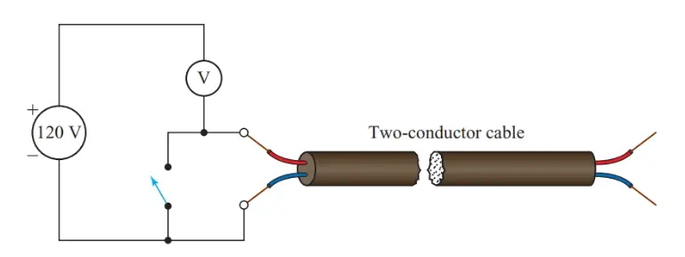
Figure 4 Using a voltmeter as a high-resistance ohmmeter
Example 3
The voltmeter in Figure 4 has a 20-kΩ /V movement. The meter reads 120 V on its 150-V scale when the switch is closed, and 10 V when the switch is open. Calculate the leakage resistance of the cable insulation.
Solution
The resistance of the voltmeter is
${{R}_{M}}=20{}^{k\Omega }/{}_{V}\times 150V=3.0M\Omega $
The voltage drop across the leakage resistance of the cable is
${{V}_{leak}}=120V-10V=110V$
Since the resistance of the voltmeter and the leakage resistance of the cable form a simple series circuit,
\[\frac{{{R}_{leak}}}{{{R}_{M}}}=\frac{{{V}_{leak}}}{{{V}_{M}}}\]
\[{{R}_{leak}}=3M\Omega \times \frac{110V}{10V}=33M\Omega \]
Wheatstone bridge
For precision resistance measurements, we can use a Wheatstone bridge as shown in Figure 5. If we adjust Ry such that there is no deflection of the galvanometer G when we close the switch, the voltage drops across Rx and RA must be exactly the same since a potential difference across the galvanometer would cause current to flow through the galvanometer. With no current through the meter movement, Ix = Iy. Hence,
\[\begin{matrix}{{V}_{x}}={{I}_{x}}{{R}_{x}} & and & {{I}_{x}}=\frac{E}{{{R}_{x}}+{{R}_{y}}} \\\end{matrix}\]
Therefore,
\[{{V}_{x}}=\frac{E{{R}_{x}}}{{{R}_{x}}+{{R}_{y}}}\]
Similarly,
\[{{V}_{A}}=\frac{E{{R}_{A}}}{{{R}_{A}}+{{R}_{B}}}\]
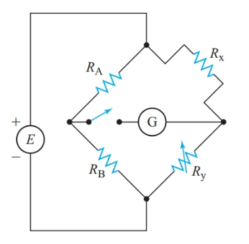
Figure 5 Measuring resistance with a Wheatstone bridge
Therefore, for perfect balance,
\[\begin{align}& \frac{E{{R}_{x}}}{{{R}_{x}}+{{R}_{y}}}=\frac{E{{R}_{A}}}{{{R}_{A}}+{{R}_{B}}} \\& {{R}_{x}}{{R}_{A}}+{{R}_{x}}{{R}_{B}}={{R}_{x}}{{R}_{A}}+{{R}_{A}}{{R}_{y}} \\& {{R}_{x}}{{R}_{B}}={{R}_{y}}{{R}_{A}} \\\end{align}\]
And
\[\begin{matrix}{{R}_{x}}=\frac{{{R}_{A}}{{R}_{y}}}{{{R}_{B}}} & {} & \left( 1 \right) \\\end{matrix}\]
For the bridge to be balanced, the product of the resistances in one pair of opposite arms of the bridge must equal the product of the resistances in other pair of opposite arms.
Since E does not appear in Equation 1, the magnitude of the source voltage used with a bridge circuit has no effect on the accuracy of the measurement. The source merely causes a deflection of the galvanometer pointer if the bridge is not properly balanced. With precision resistors for RA, RB, and Ry, we can use Equation 1 to determine an accurate value for Rx.
Example 4
The Wheatstone bridge circuit of Figure 5 is balanced when RA = 1 Ω, RB=50Ω, and Ry=17Ω. Calculate Rx.
Solution
\[{{R}_{x}}=\frac{{{R}_{A}}{{R}_{y}}}{{{R}_{B}}}=\frac{1.0\times 17}{50}=0.34\Omega \]
Summary
- An ohmmeter with a number of resistance ranges can be constructed using a moving-coil movement, a battery, shunt resistors, and series resistors.
• The Wheat stone bridge can be used for accurate measurements of resistance.
Resistance Measurement Methods Key Takeaways
The various methods for measuring electrical resistance whether for low, high, or precision measurements—are crucial in different applications, ensuring accurate and reliable electrical circuit performance. Low resistance measurements help assess components like motors and circuit connections, while ohmmeters provide quick resistance checks in troubleshooting. High resistance measurements are essential for detecting leakage currents in insulation testing, contributing to electrical safety. The Wheatstone bridge, on the other hand, is valuable in laboratories and industrial settings where precise resistance measurements are necessary.