The article discusses AC-to-AC power converter, focusing on how voltage and frequency can be modified using electronic converters, including unidirectional and bidirectional back-to-back converter configurations. It explains the role of components like rectifiers, inverters, capacitors, and inductors in these systems, and highlights their applications, particularly in wind turbines with bidirectional power flow capabilities.
For AC-to-AC conversion the voltage and/or the frequency are the parameters that might need to be increased or decreased. For voltage only, a transformer can be used. But, for the frequency change, and for both frequency and voltage change, use of electronic converters becomes necessary.
Unidirectional Back-to-Back Converters
The key issue in AC-to-AC converters is to convert AC to DC first and then DC to AC by putting together a rectifier and an inverter. Then, there is the question of if the device is required to work in one direction only, all the time, or if it must work both ways. In the former case, one side is always the input and the other side is always the output, and power always is transferred from the input to the output. In the latter case, the input and output can switch functions, and power transfer can be either way. The first case is simpler and is discussed in this section.
Figure 1 illustrates a unidirectional AC-to-AC converter. AC is first converted to DC through a rectifier that can be based on diodes or thyristors. Then, the DC electricity is converted to AC with the required frequency and voltage. Voltage control can be done through the rectifier if it is thyristor-based; otherwise, both voltage control and frequency control is done through the inverter.
The rectifier and the inverter are coupled together by a capacitor. The capacitor serves as a voltage source. In other words, there is no need for a battery to store the rectifier output. The capacitor behaves as a short-term storing device.
Alternatively, the capacitor can be regarded as a filter to smooth the output of the rectifier. The link between the two parts of the system, containing the capacitor, is referred to as the DC link.
The input can be connected to a three-phase system with a frequency fi and voltage Vi. This alternative electricity is rectified and keeps the capacitor at a voltage determined by Vi.
The DC voltage in the DC link then is converted to AC with the required frequency fo and the desired voltage Vo by using pulse width modulation or other technique. Whereas fo can be greater or smaller than fi, in general, Vo and Vi are bound through the DC link voltage. Thus, there is a limit for the maximum value that Vo can reach.
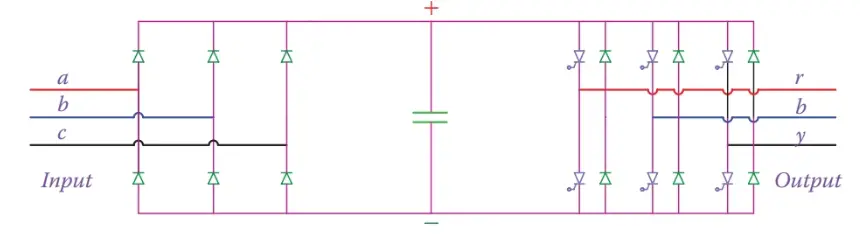
Figure 1 Unidirectional diode-based AC-to-AC converter.
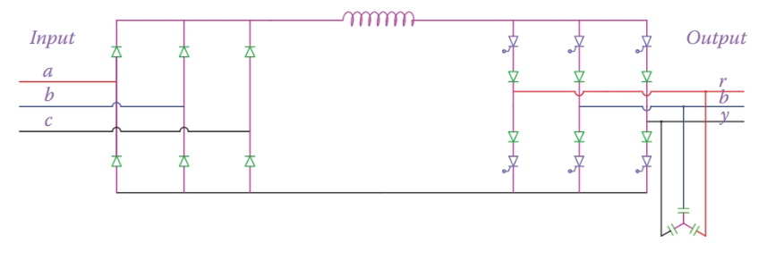
Figure 2 Diode-based unidirectional AC-to-AC Power converter with current source inverter.
It is possible to use an inductor instead of the capacitor. In such a case the inductor behaves as a short-term current source. The two terms voltage source inverter and current source inverter, used in industry, stem from whether a voltage source or a current source is used for an inverter (i.e. if a capacitor or an inductor is used in the DC link).
Figure 2 illustrates the arrangement for a current source inverter. The three capacitors in the output provide a path for the currents even if there is no load. Also, the inclusion of series diodes in series with the thyristors is to protect them (like freewheel diodes) and prevent the unwanted discharge or higher voltage at the thyristor terminals during switching.
Bidirectional Back-to-Back Converters
In many applications, including the wind turbines equipped with wound rotor induction machine (the same as DFIG), a bi-directional back-to-back converter is employed. Compared to the unidirectional converter, power can be controlled to transfer from either end to the other.
For this arrangement, it is necessary to use switchable devices for both converters. We consider only the voltage source inverters in this case because that is the type used in many of the modern wind turbines. The schematic of such a converter is shown in Figure 3.
In the circuit of Figure 3 if A, B, and C are connected to the mains with a given voltage and frequency the diodes D1 to D6 work as a rectifier to provide a DC voltage keeping the DC link capacitor charged. Then, by controlling the thyristors $T_{1}^{‘}$ to $T_{6}^{‘}$, a three-phase alternating current electricity with the required voltage and frequency can be obtained from the DC link. This AC electricity is available at A′, B′, and C′ terminals.
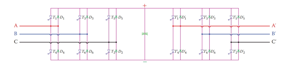
Figure 3 Schematic of a bi-directional back-to-back converter.

Figure 4 A back-to-back, a water-cooled converter in a wind turbine (partly shown).
Likewise, if alternative electricity is available at A′, B′, and C′, then this can be rectified by the three-phase rectifier consisting of diodes $D_{1}^{‘}$ to $D_{6}^{‘}$, which feeds the DC link and then a three-phase alternating current can be obtained at A, B, and C.
As can be seen, the switching actions and the voltages available at A, B, and C terminals and A′, B′, and C′ terminals (which one is larger) determine in what direction the power can transfer. Recall that the function of each converter could be defined by the firing angle of its thyristors. Thus, the operation is not automatic and must be controlled by precise timing for the signals to the gates of the thyristors (IGBTs).
Figure 4 shows some of the IGBTs and the DC link capacitors for a 1.5 MW turbine. These IGBTs are water cooled. This turbine is equipped with a DFIG; hence, it has two back-to-back converters with 12 IGBTs.
AC Power Converter Key Takeaways
Understanding AC-to-AC power converter is essential due to their wide-ranging applications in modern electrical and industrial systems. These converters allow precise control over voltage and frequency, enabling efficient power conversion and regulation in systems like motor drives, renewable energy setups, and especially wind turbines. Unidirectional converters are simpler and suitable for applications where power flow is constant in one direction, whereas bidirectional converters support flexible power flow, which is crucial in systems like doubly-fed induction generator (DFIG) wind turbines.