This article covers the fundamental principles of series circuit, including resistance, current, voltage, and power characteristics. It explains key calculations such as total resistance, voltage drops, and power dissipation.
Simply defined a series circuit is a circuit that contains only one current path. For example, consider the circuits shown in Figure 1. In each case, the current generated by the voltage source has only one path, and that path contains all of the components in the circuit.
In contrast, the parallel circuit in Figure 1b contains two current paths between the terminals of the voltage source; one through R1 and one through R2.
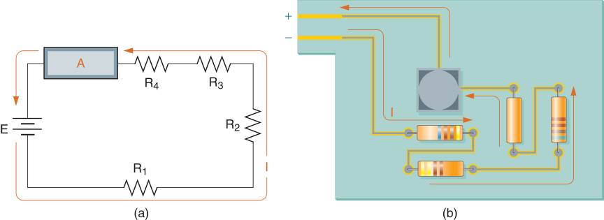
Figure 1 (a) Example series circuit schematic and construction. (b) Parallel Circuit
Resistance Characteristics
Figure 2 shows a series circuit that contains a battery and four resistors. Since the circuit current passes through all of the resistors, the total circuit resistance is equal to sum of the individual resistance is equal to the sum of the individual resistor values.
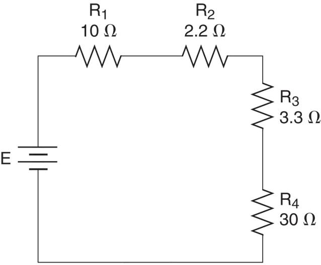
Figure 2 A four-resistor series circuit.
By Formula;
$\begin{matrix}{{R}_{T}}={{R}_{1}}+{{R}_{2}}+\cdots +{{R}_{n}} & {} & \left( 1 \right) \\\end{matrix}$
The total resistance in a series circuit is calculated as demonstrated in Example 1.
Series Circuit Example 1
What is the total resistance in the circuit shown in figure below?

Figure A four-resistor series circuit.
Solution
The total resistance is found as:
$\begin{align}& {{R}_{T}}={{R}_{1}}+{{R}_{2}}+{{R}_{3}}+{{R}_{4}} \\& =10+2.2+3.3+30=45.5\Omega \\\end{align}$
When you need to find the value of an unknown resistance in a series circuit, you can calculate it by subtracting the sum of the known resistances from the total circuit resistance. This technique is demonstrated in Example 2.
Series Circuit Example 2
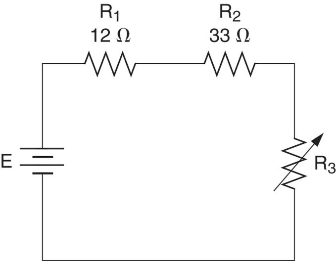
What value of R3 in Figure below will set the total circuit resistance to 120 Ω?
Solution
The combined resistance of R1 and R2 is found as:
${{R}_{1}}+{{R}_{2}}=12+33=45\Omega $
R3 must account for the difference between 45 Ω and the desired total of 120 Ω. Therefore, it must be adjusted to a value of:
${{R}_{3}}={{R}_{T}}-\left( {{R}_{1}}+{{R}_{2}} \right)=120-45=75\Omega $
As a summary, here are the series circuit resistance characteristics:
• The total resistance in a series circuit is equal to the sum of the individual resistor values.
• When the value of one resistor in unknown, it can be determined by subtracting the sum of the known resistor values from the total circuit resistance.
Current Characteristics
Because a series circuit contains only one current path, we can state that the current at any point in series circuit must equal the current at every other point in the circuit. This principle is illustrated in Figure 3.
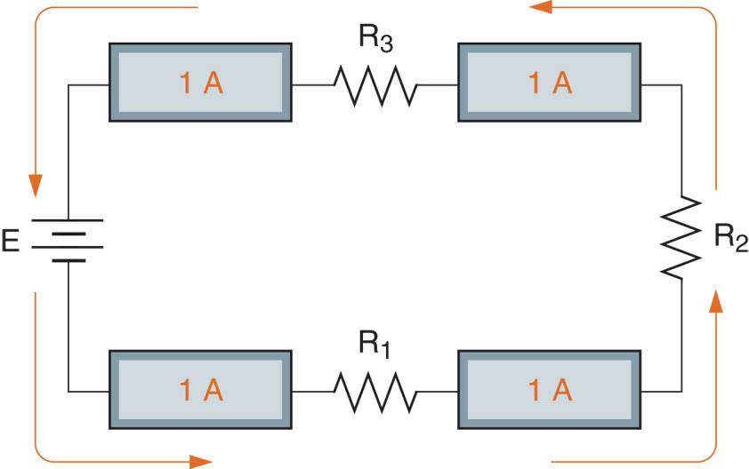
Figure 3 Current through a series circuit.
As you can see, each of the four ammeters shows a reading of 1 ampere. The fact that the meters all show the same reading makes sense when you consider the fact that current is the flow of electrons. Because electrons are leaving (and entering) the source at the rate of one coulomb per second, they must be moving at the same rate at all points in the circuit.
Figure 3 also illustrates the fact that it makes no difference where you measure the current in the series circuit. Since the current is the same at all points, you will obtain the same reading regardless of where you place the meter in the circuit.
The actual value of current in the series circuit depends on the source voltage (E) and the total circuit resistance (R1). When the source voltage and total resistance are known, Ohm’s law is used to calculate the total source circuit current. Ohm’s law is used to calculate the total circuit current, as demonstrated in Example 3.
Series Circuit Example 3
What is the value of the current through the circuit in Figure below?
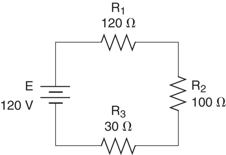
Solution
To determine the total current IT through the circuit, you begin by calculating the total circuit resistance, as follows:
$\begin{align}& {{R}_{T}}={{R}_{1}}+{{R}_{2}}+{{R}_{3}} \\& =120+100+30=250\Omega \\\end{align}$
Now, using the RT= 250 Ω and E= 100V, the total current is found as:
\[{{I}_{T}}=\frac{E}{{{R}_{T}}}=\frac{120V}{250\Omega }=480mA\]
Thus, the measured current at any point in the circuit has a value of 480 mA.
In example 2, you were shown how a rheostat can be adjusted to provide a specific value of total resistance. The following example will show how a potentiometer can be used to provide a specific value of circuit current.
Series Circuit Example 4
What adjusted value of R3 in figure below will set the value of the circuit current to 1.5 A.
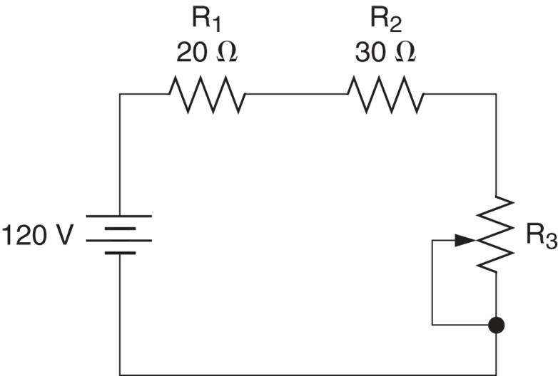
Solution
To see the circuit current to 1.5 A, we need a total resistance of
\[{{R}_{T}}=\frac{E}{{{I}_{T}}}=\frac{120V}{1.5A}=80\Omega \]
The sum of R1 and R2 is now subtracted from the value of RT to obtain the required value of R3, as follows:
${{R}_{3}}={{R}_{T}}-\left( {{R}_{1}}+{{R}_{2}} \right)=80-50=30\Omega $
Adjusting the value of R3 to 30Ω will provide a total circuit resistance of 80Ω. This resistance will set the circuit current to the desired value of 1.5 A.
As a summary, here are the series circuit current characteristics;
• The current through a series circuit is equal at all points in the circuit, and, thus, can be measured at any point in the circuit.
• The actual value of current in series circuit is determined by the source voltage and the total circuit resistance.
Voltage Characteristics
Whenever current passes through the resistance, a difference of potential (voltage) is developed across that resistance, as given by the relationship
\[V=I\times R\]
Note that the letter V is used to represent the voltage across a circuit component. That helps to distinguish component voltage from source voltages (which are represented by letter E).
Because the current in a series circuit passes through all the resistors, a voltage is developed across each resistor. For example, consider the circuit shown in Figure 4.
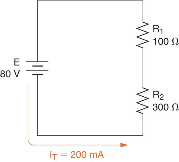
FIGURE 4 Series circuit current.
The circuit current (200mA) is shown to be passing through a 100Ω resistor and a 300Ω resistor. According to Ohm’s law, the voltage across R1 (which is designated as VR1) is found as;
${{V}_{R1}}={{I}_{T}}\times {{R}_{1}}=200mA\times 100\Omega =20V$
The voltage across R2 (which is designated as VR2) is found as:
${{V}_{R2}}={{I}_{T}}\times {{R}_{2}}=200mA\times 300\Omega =60V$
If we were to connect several voltmeters to this circuit as shown in Figure 5, we would obtain the readings shown. Note that the polarities of the component voltages are determined by the direction of the circuit current. Since electrons flow from negative to positive, the “entry” side of the component is more negative than the “exit” side. This is why the component voltages are given the polarity signs shown in the figure.
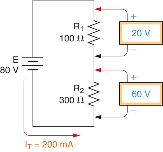
Figure 5 Series circuit current and voltages.
If you look closely at Figure 5, you’ll see that the sum of the component voltages is equal to the source (or total) voltage. This relationship, which holds true for all circuits, is given as;
\[\begin{matrix}E={{V}_{R1}}+{{V}_{R2}}+\cdots +{{V}_{Rn}} & {} & \left( 2 \right) \\\end{matrix}\]
An application of this relationship is demonstrated in Example 5.
Example 5
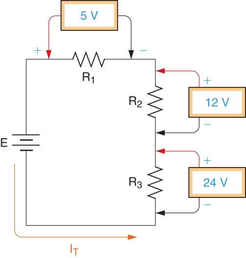
What is the value of the source voltage in figure below?
Solution
Using the components voltages, the value of the source voltage can be found as
$\text{E=}{{\text{V}}_{\text{R1}}}\text{+}{{\text{V}}_{\text{R2}}}\text{+}{{\text{V}}_{\text{R3}}}\text{=5+12+24=41V}$
In the next section, we will take a closer look at the voltage relationships in series circuits. For now, remember that the sum of the component voltage or a series circuit is equal to the source for total voltage.
Power Characteristics
When current passes through any resistance, some amount of power is dissipated by the component, as given in the relationship.
$P={{I}^{2}}R$
Since, the current in series circuit passes through all of the resistors, it would follow that they are all dissipating some amount of power. Referring back to Figure 5, the power dissipating by R1 (which is designated as PR1) is found as:
${{P}_{R1}}=I_{T}^{2}\times {{R}_{1}}={{\left( 200mA \right)}^{2}}\times 100\Omega =4W$
The power dissipated by R2 (which is designated as PR2) is found as:
\[{{P}_{R2}}=I_{T}^{2}\times {{R}_{2}}={{\left( 200mA \right)}^{2}}\times 300=12W\]
The total power dissipated by the resistance in a series circuit is equal to the total power, being supplied by the source. By formula:
\[\begin{matrix}{{P}_{S}}={{P}_{R1}}+{{P}_{R2}}+\cdots +{{P}_{Rn}} & {} & \left( 3 \right) \\\end{matrix}\]
Where
PS= total power being supplied by the source
PRn=the power dissipated by the highest numbered resistor in the circuit
For example, the total power being supplied by the source of Figure 5 is found as:
${{P}_{S}}={{P}_{{{R}_{1}}}}+{{P}_{{{R}_{2}}}}=4+12=16W$
The following example verifies the relationship given in equation 3.
Example 6
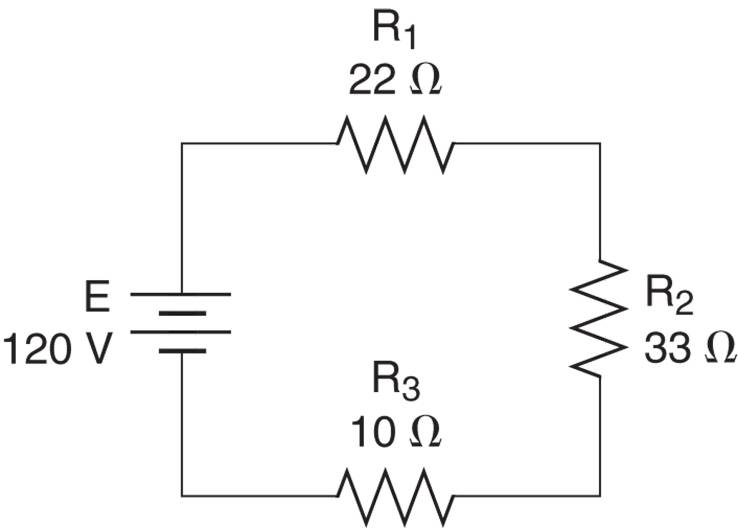
Demonstrate that the total power supplied by the source in figure below equals the sum of the resistor power dissipation values.
Solution
$\begin{align}& {{R}_{T}}={{R}_{1}}+{{R}_{2}}+{{R}_{3}} \\& =22+33+10=65\Omega \\\end{align}$
Next, the circuit current is found as
\[{{I}_{T}}=\frac{E}{{{R}_{T}}}=\frac{120V}{65\Omega }=1.85A\]
Once we know the value of the circuit current, we can find the power dissipated by each of the resistors in the circuit as follows:
${{P}_{R1}}=I_{T}^{2}\times {{R}_{1}}={{1.85}^{2}}\times 22=75.3W$
${{P}_{R2}}=I_{T}^{2}\times {{R}_{2}}={{1.85}^{2}}\times 33=113W$
And
${{P}_{R3}}=I_{T}^{2}\times {{R}_{3}}={{1.85}^{2}}\times 10=34.2W$
Adding the individual power dissipated values, the total power dissipated by the resistors is found as:
$\begin{align}& {{P}_{S}}={{P}_{{{R}_{1}}}}+{{P}_{{{R}_{2}}}}+{{P}_{{{R}_{3}}}} \\& =75.3+113+34.2=222.5W \\\end{align}$
The total power supplied by the source can also be found as
${{P}_{S}}=I_{T}^{2}\times {{R}_{T}}={{1.85}^{2}}\times 65=222.5W$
These results verify the relationship given in equation 3.
Series Circuit Analysis
The complete analysis of a series circuit involves determining the values of RT, IT, and PT, along the resistor voltage and power sources. The following example demonstrates the complete analysis of a series circuit.
Example 7
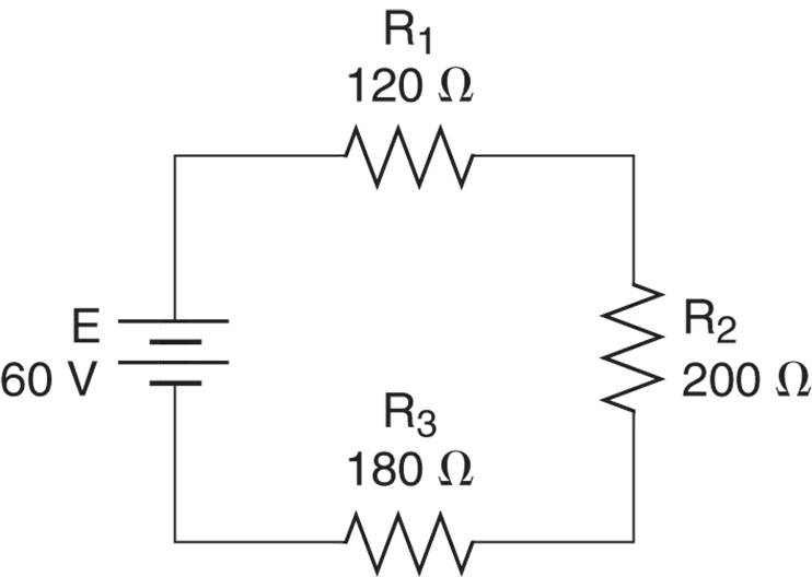
What are the current, voltage, and power values for the circuit in figure below?
Figure
Solution
The total resistance in the circuit is found as
$\begin{align}& {{R}_{T}}={{R}_{1}}+{{R}_{2}}+{{R}_{3}} \\& =120+200+180=500\Omega \\\end{align}$
Next, the total current can be found as
\[{{I}_{T}}=\frac{E}{{{R}_{T}}}=\frac{60V}{500\Omega }=120mA\]
The total power drawn from the source can be found as
${{P}_{S}}=E\times {{I}_{T}}=60V\times 120mA=7.2W$
The voltage across each resistor can be found by Ohm’s Law, as follows:
${{V}_{R1}}={{I}_{T}}\times {{R}_{1}}=120mA\times 120\Omega =14.4V$
${{V}_{R2}}={{I}_{T}}\times {{R}_{2}}=120mA\times 200\Omega =24V$
And
${{V}_{R3}}={{I}_{T}}\times {{R}_{3}}=120mA\times 180\Omega =21.6V$
The individual power dissipation values for the resistors can now be found as:
${{P}_{R1}}={{V}_{R1}}\times {{I}_{T}}=14.4V\times 120mA=1.73W$
${{P}_{R2}}={{V}_{R2}}\times {{I}_{T}}=24V\times 120mA=2.88W$
And
${{P}_{R3}}={{V}_{R3}}\times {{I}_{T}}=21.6V\times 120mA=2.59W$
This completes the circuit calculations.
The component voltage and power dissipation values found in the example can be verified by comparing their sums to the source voltage and total power as;
${{V}_{R3}}+{{V}_{R3}}+{{V}_{R3}}=14.4+24+21.6=60V$
And
${{P}_{{{R}_{1}}}}+{{P}_{{{R}_{2}}}}+{{P}_{{{R}_{3}}}}=1.73+2.88+2.59=7.2W$
These values (E= 60V and PT = 7.2W) verify that the component voltage and power dissipation values calculated in the example are correct.
Summary
Resistance: A series circuit is one that contains a single path for current. The total resistance in a series circuit is equal to the sum of the individual resistor values.
Current: The total circuit current is the same at every point in the circuit, and is generally found by dividing the source voltage by the total circuit resistance.
Voltage: When current passes through the resistors in series circuit, a voltage is developed across each resistor. The sum of these voltages is equal to the circuit’s source voltage.
Power: The current through the resistors in a series circuit also causes each component to dissipate some amount of power. The sum of the component power dissipation values is equal to the total power supplied by the source.
The resistance, current, voltage, and power characteristics are summarized in Figure 6.
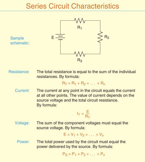
Figure 6 Series Circuit Characteristics
Series Circuit Characteristics Key Takeaways
Understanding series circuits is crucial for various practical applications, including electronic device design, power distribution, and circuit troubleshooting. The ability to calculate total resistance, current, voltage drops, and power dissipation allows engineers and technicians to design efficient and safe electrical systems. Series circuits are widely used in devices such as string lights, sensors, and battery-powered circuits, where maintaining a consistent current is essential.