The article explains types of network topology, including Bus, Star, Ring, Mesh, and Hybrid, along with their advantages and disadvantages. It also covers networking models, hardware components, and different area networks (LAN, WAN, MAN).
By the end of this article, you will be able to:
- Describe the TCP/IP model and its relationship with the OSI model.
- Describe the items that exist on a network.
- Explain the concept of host virtualization.
- Compare the various types of network models and topologies.
Networking Models
The Transmission Control Protocol and Internet Protocol (TCP/IP) Model consists of four layers. It is important to remember that the TCP/IP is a two-way model (up and down data flow).
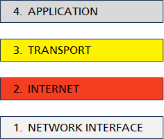
Figure 1 TCP/IP Model
1. Network Interface: The Network Interface layer is also known as the Link Layer. It describes how a host accesses the network. For example, copper wire (Ethernet), fiber optics, or radio spectrum (wireless).
2. Internet: The Internet layer determines the routing decisions based on the protocol being used and the information in the data packet.
3. Transport: The Transport layer ensures protocols are followed in host-to-host communications.
4. Application: The Application layer is responsible for the protocol needed for an application to run. It specifies which ports and sockets are needed for the application.
A good way to think about the TCP/IP model is a condensed version of the Open Systems Interconnection (OSI) model, where some layers are combined into one. See Figure 2 to review the TCP/IP layers and how they coincide with the four OSI layers: 1) Data Physical Link, 2) Network, 3) Transport, and 4) Application Presentation Session.
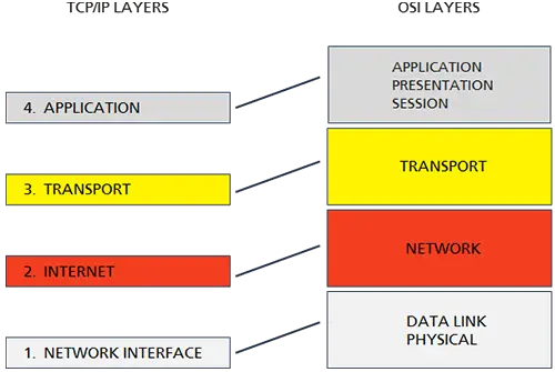
Figure 2 OSI Data Flow: Representations of TCP/IP and OSI Layers
Hardware Components of a Computer Network
In the following section, you will learn about the components that comprise a computer network. A is a device connected to a network is a host. A host serves some kind of purpose on the network no matter how unsophisticated.
A host can be a number of things: computer workstation, phone (VoIP), printer, server, router, switch (multilayer), hub, bridge, and repeater.

A computer workstation can be a Desktop or Laptop computer commonly used for personal use. Their purpose can be business, recreational or both. An organization may have several computer workstations “attached” or running on their network.

A VoIP telephone uses an Ethernet connection in order to place and receive calls. This functionality is different from traditional phone systems which use Plain Old telephone service (POTS) lines.

Network printers allow for multiple users within an organization to print. This is different from local printers where only the person attached via a serial cable could print at a time.
Servers are computational systems with expanded resources needed to provide service to clients (i.e. computer workstations) on a network. They will typically have more memory, hard drive space, and processor cores, as well as advanced software and interface cards.
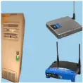
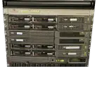
Routers are used to direct data traffic through different network segments and are often located near the network perimeter. Routers are also used to pass data packets through the internet to a given destination. The tall beige router with the green tag is one of the first routers ever developed for ARPANET. Other more modern and Wireless Routers are seen here as well. In data centers or highly connected environments, it is common to see routers in a network rack.
![]()
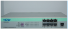
The network switch is used to interconnect multiple hosts on a network. A switch has some intelligence built into it. A switch can map the media access control (MAC) addresses of hosts connected to its ports. When data comes into the switch, it can direct that traffic to a specific port where the destined host is located.
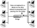
A bridge joins two separate networks into one. This functionality can be accomplished using a network switch.
A network hub is also used to connect host on a network, however, they are not used in highly active environments. Hubs have no intelligence built into them and can often drop packets in a highly active networks. Hubs have one collision domain, meaning no matter how many devices you have connected, only one is allowed to use the media at one time. Hosts connected to a hub may try to send and receive at the same time, which will create a collision and data packets can get “lost” or drop.

A wireless repeater is used when a wireless (RF) signal is weak and needs to be amplified. The wireless repeater extends the range of a wireless signal. For example, if a wireless signal has a range of 50 meters and you were 75 meters away, you could use a wireless repeater to connect.
Virtualization
A virtual switch can shape and control network traffic, and employ protective measures against other virtual machines. Virtual switches are often used within virtualization products like Hyper V and VMware.
Offsite hosting is similar to a hosted environment where someone else manages your servers on their network. Whereas, in an onsite environment your organization supplies the network resources, servers, and employees needed to manage the equipment.
Organizations may consider using offsite hosting for a lower cost vs. hosting onsite which will have higher costs and overhead expenses. Review the following list of key facts that are important to be aware of.
Key Facts

- Virtual systems run on top of physical systems or appliances.

- Virtual Desktops and Servers can be run using software. (i.e. Citrix, VMware, HyperV, etc.)

- A Virtual Switch uses software to emulate the same functions of a physical switch.

- The Internet enables the ability to route calls using the Internet (IP addressing) vs. physical wiring - a virtual or hosted PBX.

- Network as a Service (NaaS) – entails using a third-party provider for network resources. Offsite cloud technology.
Network Models in Computer Networks
There are network models and topologies which describe how computational systems communicate and interconnect with each other.
The most popular network model is the Client–Server model. The Client–Server model describes when a computer system processes requests from other computer systems and is used for large networks, centralized administration, and security, and provides performance benefits.
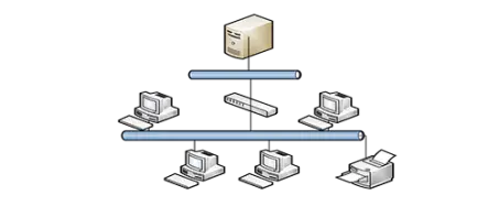
Figure 3 Client-Server Model Diagram in Computer Networking
The other well-known network model is the Peer-to-Peer model. The Peer-to-Peer model describes when each computer system on the network can request or processes request from other computers. The benefits this model provides for large networks are performance, security, and centralized administration. A Peer-to-Peer model is easy to set up, used for small networks, and decentralizes administration.
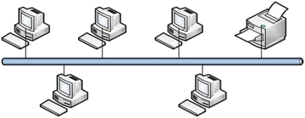
Figure 4 Peer-to-Peer Model Diagram in Computer Networking
Network Topology Types with Diagrams
Network topologies can be viewed as a “MAP” of the network. It shows how the nodes interconnect. The Institute of Electrical and Electronic Engineers (IEEE) sets the standards for computer network technology. There are five network topologies identified below: Bus, Token Ring, Star, Mesh, and Hybrid.
Bus Topology in Computer Network
Bus topology is one of the simplest forms of network architecture, where all devices are connected to a single communication line called the “bus” or backbone. The bus serves as a shared transmission medium, allowing devices to send and receive data sequentially. When a device transmits data, the signal propagates along the bus and is received by all connected devices. However, only the intended recipient processes the data, while others ignore it.
A terminator is attached to both ends of the bus to prevent signal reflection, which could cause data interference. Bus topology typically uses coaxial or fiber-optic cables for data transmission. Protocols like Carrier Sense Multiple Access with Collision Detection (CSMA/CD) are often used to manage data collisions.

Figure 5 Bus Topology Diagram in Computer Network: Black lines indicate endpoints.
Token Ring Topology in Computer Network
Token ring topology organizes network devices in a logical circular structure, where data flows unidirectionally between them. A special data packet called a “token” circulates through the ring. A device must acquire the token to transmit data, ensuring orderly communication and preventing data collisions.
Each device in the ring acts as a repeater, regenerating and passing the token and data to the next device. The logical circular connection can be implemented physically in a ring or using centralized hardware like a Multi-Station Access Unit (MSAU).
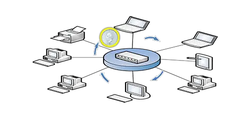
Figure 6 Token Ring Topology Diagram in Computer Network
Star Topology in Computer Network
In star topology, all devices are connected to a central hub, switch, or router using dedicated communication lines. The central hub acts as the mediator, receiving data from one device and forwarding it to the intended recipient. Devices in this topology do not communicate directly, ensuring structured data transfer.
The central device plays a crucial role in managing data traffic and isolating faults. Star topology is widely used in modern Local Area Networks (LANs) and wireless networks due to its efficiency and reliability.
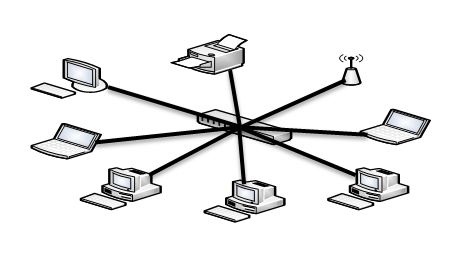
Figure 7 Star Topology Diagram in Computer Network
Mesh Topology in Computer Network
Mesh topology creates a network where devices (nodes) are interconnected, forming multiple communication paths. It can be categorized into:
- Full Mesh: Every node is directly connected to all other nodes.
- Partial Mesh: Some nodes are interconnected, while others are not directly linked.
This topology provides high redundancy and reliability. If one connection fails, data can take alternative routes to reach its destination. Mesh networks are common in mission-critical applications, such as military communication systems and financial infrastructures.

Figure 8-1 Mesh Topology Diagram in Computer Network
Hybrid Topology in Computer Network
Hybrid topology combines two or more topologies, leveraging their strengths to meet specific network requirements. For example, a hybrid network may integrate star and bus topologies, using a central hub to connect star-configured subnets to a bus backbone.
This topology is highly versatile and can be customized for various use cases, making it ideal for large, dynamic environments like corporate offices or university campuses.
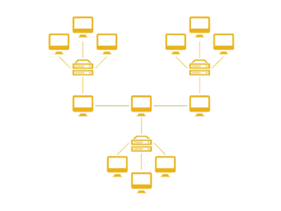
Figure 8-2 Hybrid Topology (Star-Bus topology) Diagram in Computer Network
Network Topology Advantages and Disadvantages
| Topology | Advantages | Disadvantages |
|---|---|---|
| Bus Topology | – Cost-effective and easy to set up. | – Difficult to troubleshoot. |
| – Ideal for small networks. | – Performance decreases with more devices. | |
| Token Ring | – Prevents data collisions using token-based access. | – Slower than other topologies in high-demand networks. |
| – Deterministic performance. | – Failure of one device can affect the entire network. | |
| Star Topology | – Easy to add/remove devices. | – Failure of the central hub disrupts communication. |
| – Centralized management and fault isolation. | – Requires more cabling compared to bus topology. | |
| Mesh Topology | – High redundancy and fault tolerance. | – Expensive due to extensive cabling. |
| – Ideal for mission-critical systems. | – Complex installation and maintenance. | |
| Hybrid Topology | – Combines the strengths of multiple topologies. | – Complex to design and manage. |
| – Scalable and flexible. | – Cost can increase depending on the design and components used. |
Area Networks Types in Computer Network
Computer networks are classified based on their geographical coverage and functional scope, allowing them to cater to different needs and environments. Below, we provide a detailed explanation of the main types of area networks: LAN, WLAN, CAN, MAN, and WAN, highlighting their technical characteristics, advantages, and typical applications.
Local Area Network (LAN)
A Local Area Network (LAN) is a computer network that connects devices within a limited geographical area, such as a home, office, school, or campus. LANs are designed to facilitate high-speed communication and resource sharing among devices like computers, printers, and servers. Typically, LANs use Ethernet cables or wireless connectivity for data transmission. They often employ star or bus topologies, with switches and routers serving as the backbone of the network infrastructure. Ethernet-based LANs (IEEE 802.3) support wired connections, while wireless LANs operate on Wi-Fi standards (IEEE 802.11).
Transmission speeds in LANs can range from 100 Mbps to 10 Gbps, ensuring efficient handling of local data traffic. Due to their confined scope, LANs are relatively easy to set up and maintain, making them cost-effective and highly reliable for small-scale networking.
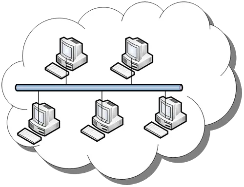
Figure 9 LAN – Local Area Network (i.e. Office Building)
Wireless Local Area Network (WLAN)
A Wireless Local Area Network (WLAN) is an extension of LAN that uses wireless communication technology instead of cables for device connectivity. WLANs rely on radio frequency (RF) signals to establish communication between devices and access points, providing flexibility and mobility for users. Operating under the IEEE 802.11 standards, WLANs are commonly deployed in homes, offices, and public spaces like cafes and airports. They enable users to connect multiple devices, including laptops, smartphones, and IoT devices, without the need for physical cabling.
WLANs generally cover a radius of up to 150 feet indoors and more in outdoor environments. However, wireless communication is prone to interference and may have lower data transmission speeds compared to wired LANs. Security protocols like WPA2 or WPA3 are crucial to protect WLANs from unauthorized access and data breaches.
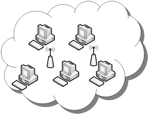
Figure 10 WLAN – Wireless Area Network (i.e. Wireless LAN)
Campus Area Network (CAN)
A Campus Area Network (CAN) spans a larger geographical area than a LAN, such as a university, corporate campus, or industrial park. It connects multiple buildings or departments within a campus-like environment, forming a unified network that supports high-speed communication and data sharing. CANs typically use a combination of fiber optics and Ethernet cables for robust and reliable connectivity. They often integrate multiple LANs into a cohesive structure, with a central backbone for managing traffic.
The primary purpose of a CAN is to facilitate seamless communication and resource sharing between various facilities, such as labs, libraries, and administrative offices. CANs are cost-effective compared to Wide Area Networks (WANs) because they cover a limited area and are managed internally. However, they require specialized planning and management to ensure smooth operation across the network.
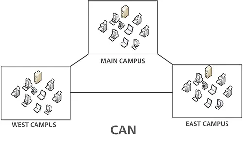
Figure 11 CAN – Campus Area Network (i.e. University Campus)
Metropolitan Area Network (MAN)
A Metropolitan Area Network (MAN) is a network that spans a city or a large metropolitan area. MANs are designed to interconnect multiple LANs within a city, providing high-speed communication and resource sharing over a broader geographic area. They often use fiber-optic cables and technologies like Multiprotocol Label Switching (MPLS) or Asynchronous Transfer Mode (ATM) for efficient data transmission. Typical applications of MANs include connecting government institutions, universities, and large enterprises across different locations within the same city.
With data speeds ranging from 10 Mbps to several Gbps, MANs are ideal for supporting applications that require significant bandwidth, such as video conferencing and cloud computing. Despite their extensive coverage, MANs are limited to city-scale operations and are more complex to manage than LANs.
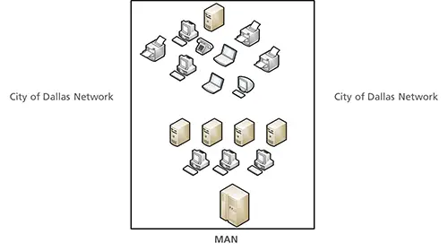
Figure 12 MAN – Metropolitan Area Network (i.e. City limits)
Wide Area Network (WAN)
A Wide Area Network (WAN) is the largest type of computer network, covering vast geographical areas such as countries, continents, or even the entire globe. WANs connect multiple smaller networks, including LANs and MANs, to enable long-distance communication and data transfer. The internet is the most prominent example of a WAN. These networks rely on technologies like satellite links, leased lines, and public telecommunications infrastructure to maintain connectivity. Protocols such as Frame Relay, MPLS, and IPsec are commonly used to manage WAN traffic.
WANs are essential for organizations with distributed offices and global operations, allowing seamless data sharing and collaboration. However, WANs are expensive to set up and maintain due to their reliance on external service providers and advanced infrastructure. Additionally, they may experience higher latency compared to local networks.
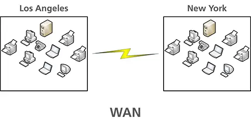
Figure 13 WAN – Wide Area Network (i.e. New York to Chicago)
Network Topology Key Takeaways
- This article introduced the physical and virtual network components. The information covered various objects which will help when discussing different types of network models and topologies.
- The TCP/IP model along with two common network models were described, the Client–server and Peer-to-Peer network models. The article explained the models and relating them to physical systems helped one see how each host, and workstation, makes up a network.
- Different types of network topologies were also discussed to provide an idea of the various ways a network can be constructed and the scope or range they have.