The article explains the working principle of buck-boost transformers, which adjust voltage levels by either increasing (boosting) or decreasing (bucking) the supply voltage using specific wiring configurations and transformer polarities. It also covers practical applications, wiring methods, and the role of transformer polarity dots in indicating phase relationships.
A buck-boost transformer is a type of transformer which is primarily used to adjust the voltage level applied to various electric equipment. Buck-boost transformers are utilized in in several applications such as uninterruptible power supplies (UPS) units for computers.
When an existing AC electrical circuit suffers from excessive voltage drop along the length of the conductors, a conventional transformer, given the correct primary and secondary voltage ratings, can be wired as an autotransformer to boost the sagging voltage. The polarities of the two series-connected windings would have to be configured in additive polarity to add the lower secondary winding voltage to the primary-winding / line voltage.
When the AC distribution voltage within a building or other structure is of higher voltage rating than the voltage rating of a unit of electrical utilization equipment, a conventional transformer, given the correct primary and secondary voltage ratings, can be wired as an autotransformer to buck the too-high system voltage. The polarities of the two series-connected windings would have to be configured in subtractive polarity to subtract the lower secondary winding voltage from the primary winding/line voltage.
Transformer Polarities (The Dots)
To understand what is meant by transformer polarities, you must consider the voltage produced across a winding by a single-phase 2-wire AC sine waveform at some point in time. When a building or other structure electrical-power distribution circuit operates at 60-Hz AC. The voltage as indicated in Figure 1, changes polarity a total of 120 times per second. Transformer polarity involves the relationship between the different windings at the same point in time. When investigating winding polarity, it is assumed that this point in time occurs when the peak positive voltage is being produced across both windings in question.
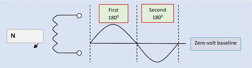
Figure 1. Generation of a single-phase 2-wire AC sine waveform electrical supply from a rotating magnetic field
On a wiring diagram (whether an electrical drawing or on the nameplate of a buck or boost transformer), it is common practice to indicate the polarity of the transformer windings by placing a solid black dot beside one end of each winding as shown in Figure 2. These dots (bullets) signify that the polarity is at the same point in time for each winding. Another way to describe winding polarity is to say the two winding-voltage waveforms are in phase. This same type of polarity notation is also used for transformers that have more than one primary or more than one secondary winding.

Figure 2. Diagram of the single-phase AC transformer circuits with dots indicating winding polarity
The windings of a conventional (isolating) transformer can be tested for the buck or boost wiring configuration by connecting the primary and secondary windings as an autotransformer as shown in Figure 3, and testing for either additive or subtractive polarity.
When additive-polarity connections are used to increase a too-low circuit voltage, the circuit is normally referred to as a boost configuration, because the secondary winding voltage is added to the line or supply voltage (to “boost” the primary winding voltage).
When subtractive-polarity connections are used to decrease a too-high circuit voltage, the circuit is normally referred to as a buck configuration, because the secondary winding voltage is subtracted from the line or supply voltage (to “buck” the primary winding voltage). Either boosting or bucking the supply voltage is accomplished by connecting one lead of the secondary winding to one lead of the primary winding and applying the voltage across both windings to the connected load.
The transformer shown in Figure 3 has a primary voltage rating of 120 volts and a secondary voltage rating of 30 volts. Notice that neither the primary nor secondary windings are lead or polarity identified and that the secondary winding has been connected in series with the connected load. The transformer now contains only one winding and is, therefore, an autotransformer.
When the 120-volt supply is applied to the primary winding, the voltmeter connected across the load will indicate either the sum of the two winding voltages (boost configuration) or the difference between the two winding voltages (buck configuration). If the voltmeter readout is 150 volts, the primary and secondary windings are connected in additive polarity (120V + 30V = 150V). If the voltmeter readout is 90 volts, the primary and secondary windings are connected in subtractive polarity (120V – 30V = 90V).
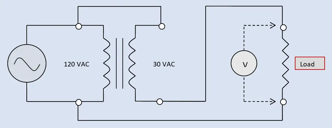
Figure 3. Diagram of a single-phase AC transformer connected as an autotransformer for either buck or boost configuration
When the polarity dots are not shown on a given transformer-wiring diagram with the respective-circuit lead identification, it is normally assumed that H1 in the primary (or the higher-voltage winding for step-down configuration) and X1 in the secondary (or the lower-voltage winding for step-down configuration) are in phase (have the same transformer winding polarity). Some schematics shown the H1 and X1 lead with the accompanying polarity dots. Polarity dots are always used when the H1 and X1 leads are not of the same polarity — to show which identified winding leads are of the same polarity.
The basic boost or buck circuit of Figure 3 is drawn expanded in Figures 4 and 5 to show the polarity aspects of the primary and secondary windings.
Single-Phase Boost Transformers
A voltage-boost situation could arise when a 230-volt, single-phase AC induction motor is installed on a 200-volt power supply. At the lower-voltage rating, the motor would overheat, even under light-loading conditions.
As shown in Figure 4 an isolation transformer with a 200-volt primary and a 30-volt secondary can be wired to deliver 230 volts to the motor. The boost operation occurs when the 30-volt secondary winding is wired in additive polarity with the 200-volt primary winding. The 30-volt secondary voltage is effectively added to the 200-volt primary voltage. The motor load receives 230 volts.
Another typical application of this boost configuration is to correct for voltage drop on a distant motor load, such as a rural well pump, where both the circuit supply and the motor are rated at 230 volts, but the circuit conductors were not sized correctly to compensate for the voltage drop on initial installation, and replacement of the circuit conductors is cost prohibitive. The circuit current in this boost application will increase the existing load current drawn from the branch-circuit supply. The increase in the supply-circuit load current will equal the current drawn by the primary winding of the transformer. The boost operation of the transformer will convert the current in the primary winding operating at the lower supply-line voltage, to the secondary winding voltage that will add to the lower supply-line voltage at the original motor-load current value in the secondary circuit.
If the full-load current rating of the AC electric motor in Figure 4 is 8 amps, this 8 amps flows through the 30-volt winding of the transformer which is in series with the motor.
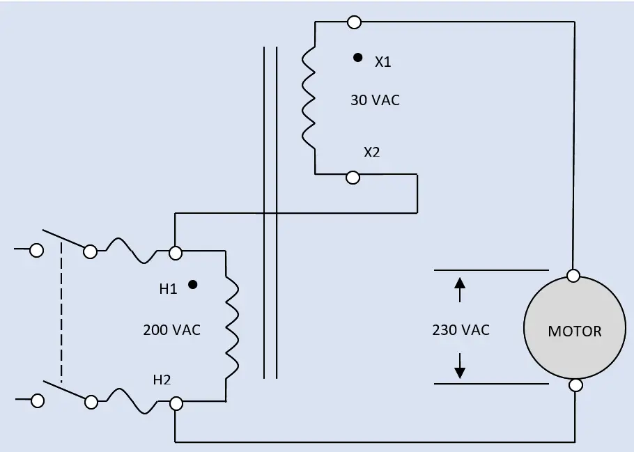
Figure 4. An isolation transformer can be wired as an autotransformer in a boost configuration
Projected into the primary winding circuit by the inverse of the voltage ratio:
(30 volts ÷ 200 volts) × 8 amps = 1.2 amps
The primary winding full-load current, to provide an increase in the secondary circuit of 30 volts, requires 1.2 amps. From the branch-circuit supply, the two currents add:
8 amps + 1.2 amps = 9.2 amps
Both the AC electric motor and the transformer are allowed to operate in a 125% overload condition:
125% of 9.2 amps = 11.5 amps
Using the next higher standard size, the boost transformer and the motor circuit would both be protected by a fuse or circuit breaker rated at 15 amps. The transformer’s minimum power rating would be based on the motor’s full-load current rating and the secondary voltage rating of 30 volts:
30 volts × 8 amps = 240 volt-amps
In Figure 4, the secondary winding has been connected in series with the connected load with secondary (or lower-voltage) lead X2 connected to one side of the transformer/load power supply and the primary (or higher-voltage) lead H1. Leads H1 and X1 are polarity dotted, indicating these two points in the transformer circuit are in phase. The H1 – X2 connection is a dot ‒ to ‒ no-dot connection, which should yield additive polarity. The load voltage, indicated by the voltmeter readout, is the sum of the 200-volt branch-circuit supply / primary voltage rating and the 30-volt secondary voltage rating: 230 volts.
Single-Phase Buck Transformers
A buck situation could arise when a 208-volt, single-phase AC resistive load must be installed on a 277-volt power source (branch circuit). At the higher-voltage rating, the resistive load would overheat to the point of destruction or at least damage to the heating elements. As shown in Figure 5, an isolation transformer with a 277-volt primary and a 69-volt secondary can be wired in a buck configuration to deliver 208 volts to the resistive load. The buck operation occurs when the secondary winding is wired in subtractive or reverse polarity to the primary winding. The 69-volt secondary voltage is effectively subtracted from the 277-volt primary voltage. The resistive load receives 208 volts.
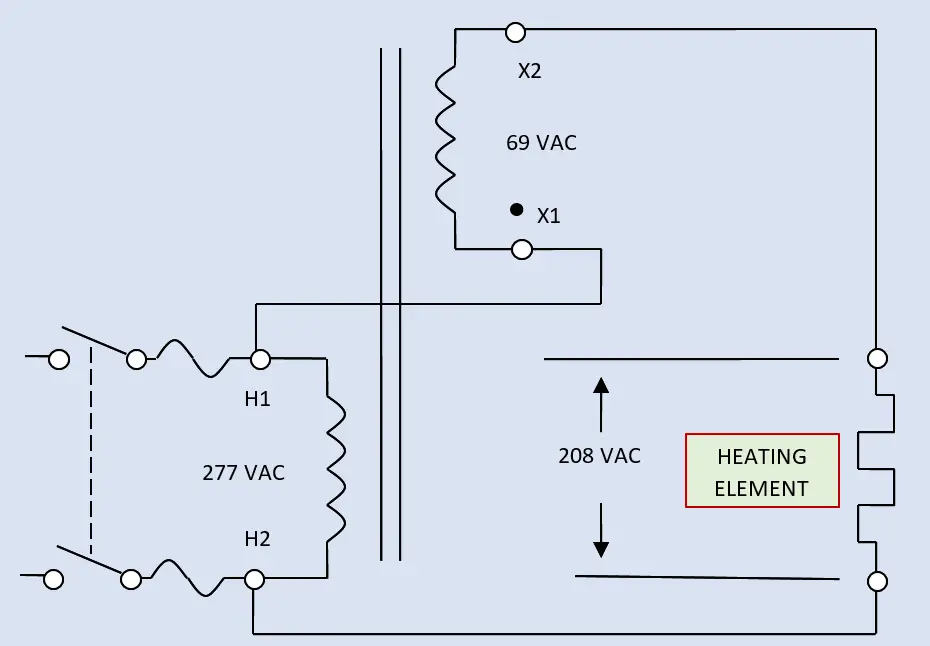
Figure 5. An isolation transformer can be wired as an autotransformer in a buck configuration
If the resistive heating load in Figure 5 is rated at 10 kW, the full-load current is calculated as:
[1000 (/k) x 10 kW] ÷ 208 volts = 48.1 amps
The 48.1 amp heater current will flow through the 69-volt winding that is in series with the heater assembly. Projected into the primary circuit by the inverse of the voltage ratio:
(69 volts ÷ 277 volts) × 48.1 amps = 12.0 amps
The primary full-load current, to provide a decrease in the secondary circuit of 69 volts, requires 12.0 amps. Since the secondary winding is wired in subtractive polarity (indicated by the winding jumper being interconnected between H1 and X1), the 12-amp primary is effectively subtracted from the secondary load amperage to calculate the branch-circuit supply current:
48.1 amps – 12 amps = 36.1 amps
The power ratings of the two transformer circuits are equal:
277 volts × 36.1 amps = 208 volts × 48.1 amps = 10,000 volt-amps
The circuit for both the resistive heating load and the transformer are sized at 125% of these calculated full-load current ratings. The calculated branch-circuit OCPD rating is:
125% of 36 amps = 45 amps
The calculated primary-circuit current is:
125% of 12 amps = 15 amps
The calculated secondary-circuit current, which includes both the secondary winding and the heating assembly, is:
125% of 48 amps = 60 amps
In Figure 5 the secondary winding has been connected in series with the connected load with secondary (or lower-voltage) lead X1 connected to one side of the transformer/load power supply and the primary (or higher-voltage) lead H1. Leads H1 and X1 are polarity dotted, indicating these two points in the transformer circuit are in phase. The H1 – X1 connection is a dot-to-dot connection, which should yield subtractive polarity. The load voltage, indicated by the voltmeter readout, is the difference of the 277-volt supply/primary voltage rating and the 69-volt secondary voltage rating: 208 volts.
As a general rule, autotransformers cannot be used to supply individual branch or feeder circuits, unless the common lead connection is to the grounded-circuit conductor in a 2-wire branch circuit.
Buck-Boost Transformer Key Takeaways
Understanding buck-boost transformers and their wiring configurations is crucial because these devices play an essential role in ensuring that electrical equipment receives the correct voltage for safe and efficient operation. By either increasing (boosting) or decreasing (bucking) voltage levels, buck-boost transformers protect sensitive devices from damage due to undervoltage or overvoltage conditions, which commonly occur in various practical applications such as motor operation, heating elements, and uninterruptible power supplies (UPS). Proper use of transformer polarity and correct wiring techniques ensures that voltage adjustments are accurate and reliable. This makes buck-boost transformers indispensable in industrial, commercial, and residential electrical systems where maintaining stable voltage is vital for performance, safety, and longevity of electrical loads.