The article discusses elementary electrical diagrams used to represent control sequences in electrical circuits, focusing on the use of standardized symbols for both DC and AC systems. It also covers their application in building power distribution, including grounding practices and conductor color-coding for safety and identification.
When the circuit components are either large, remote from each other, or numerous in a given electrical-power distribution system or control process drawing, the pictorial wiring diagram is an ineffective way to relay the required information. A different type of drawing, called the elementary diagram, which displays only the electrical control sequence, is normally used. The electrical sequence of events is presented in the most straightforward method possible.
In the elementary diagram, symbols, instead of a picture or likeness, are used for the circuit components. Symbols are like a second language in the electrical field.
The way the symbol is drawn is intended to relay its function. Its location in the line drawing, the line indicating the conductor or connecting wire, relates its electrical location in terms of the control sequence instead of its physical location.
DC Circuit Elementary Diagrams
Figure 1 shows the lighting circuit drawn using symbols for the circuit components. The symbol for the DC battery is used to relate both the battery polarity and its output voltage.
The first long crossbar (top-to-bottom) identifies the positive terminal of the battery. The last short crossbar identifies the negative terminal. A long and short crossbar pair indicates an individual cell in the storage battery. In terms of voltage, each individual cell can normally produce 1.5 volts. Counting the number of cells drawn in the symbol determines the available battery voltage.
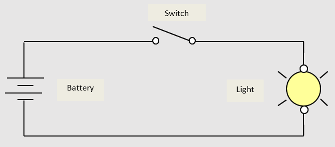
Figure 1. Elementary diagram of a basic DC electrical circuit
The switch is drawn as a 2-position toggle switch. In the open position (as drawn), all the supply voltage is dropped across the switch terminals, which interrupts the power available to the light. In the closed (or activated) position, the switch offers low resistance to the flow of electrical current: The supply voltage is dropped across the luminaire terminals. The light glows (or is turned on).
The switch symbol indicates the two wire terminals as two small circles. The switching action is shown as a single bar (knife blade) hinged on one terminal. The closing of the switch causes the single bar to touch the second terminal and establish circuit continuity.
The light is drawn as a larger circle (when compared to a wire-terminal symbol). To represent the radiance of a burning light, two diagonal lines (450 angle lines) are drawn across the center of the circle. To reduce confusion and still convey the information, the diagonal lines are drawn as extended outside the circle, but not inside.
AC Circuit Elementary Diagrams
If the DC battery is replaced with an AC source, another symbol is required. Figure 2 is the same lighting circuit as depicted in Figure 1 with an AC source.
A large circle in an elementary diagram (as used here for the AC source) normally indicates an enclosure that contains other electrical components. The circle for the AC source should be drawn larger that the circle for the light. The diagonal lines, extended from the circle, symbolize the light. The small sine wave inside the other circle symbolizes the AC source.
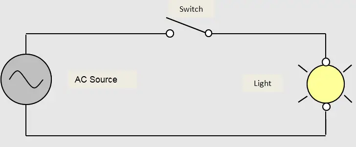
Figure 2. Elementary diagram of a basic AC electrical circuit
The sine wave represents one complete cycle of the alternating-current source. The symbol might represent conditioned AC power available from the terminals of a regulated power supply. It might also represent the distribution electrical power available from either the convenience receptacle in a given room of a building, or from the circuit breaker or fused-switch source of the branch-circuit located in the service equipment or other load center of the building electrical-power distribution system. Both Figures 1 and 2 are often used in circuit analysis of ACD and DCA fundamentals.
Building Electrical Power Distribution Elementary Diagrams
When the elementary diagram represents switched lighting in the electrical-power distribution system of a building, it is normally referenced to earth ground for protection against lightning or other voltage surges, the AC source is normally shown in greater detail in this elementary diagram.
The ungrounded supply circuit conductor is normally shown as sourced from a fused knife switch. The grounded circuit-return conductor is normally shown with another symbol ― connected to earth ground. Figure 3 shows the same lighting circuit depicted in Figure 2 with the branch-circuit AC source of the electrical-power distribution.
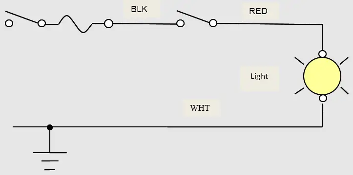
Figure 3. Elementary diagram of a lighting circuit in a building electrical-power distribution system
The symbol of the 2-position (ON/OFF) selector switch is also used to represent the knife-switch disconnecting means. The lazy S symbol on the load side of the knife switch indicates a thermal fuse element.
Insulated circuit conductors must always be protected from overheating due to an overcurrent condition in the circuit. Sometimes the fuses, especially power fuses are drawn as a rectangle with a crossbar at each end inside the rectangle to represent the end caps of the cartridge fuse.
An individual fuse holder would be drawn with a wire terminal (open circle) on both its line and load sides. When the fuse holder is part of the knife-switch assembly (fused knife switch), only a single open circle is used to indicate a screw-terminal connection between the load side of the knife switch and the line side of the fuse holder.
The symbol for earth ground is shown connected to the grounded circuit-return conductor with a solid dot or circle (also referred to as a “bullet”). At the switch location, the grounded circuit conductor in the homerun (between the supply and the lighting-outlet location) is shown connected to the downstream-feed grounded circuit conductor with a bullet to indicate the splice.
In comparison to the open circle on the switches, which indicates a screw-terminal connection, the solid circle (dot or bullet) normally signifies a splice with some type of fastener (wire nut, crimp-sleeve, or some other pressure device).
Circuit-Conductor Color-Coding
Another important concern is indicated with this elementary diagram: the color-coding of the circuit conductors. Because the supply, control point, and connected load are located remote from each other in this application, the required circuit conductors (both grounded and ungrounded, as well as the non-circuit equipment-grounding conductor) must be color-coded to indicate their purpose or function. Also, the color-coding aids in distinguishing one from the other.
Equipment-grounding conductors, which are the safety net of the circuit, are not current-carrying conductors under normal circuit operation. These non-circuit conductors, which are purposely held at ground reference, can be bare. When insulated or covered, these conductors must be color-coded green, or green with one or more yellow stripes as shown in Figure 4.

Figure 4. Identification of the circuit conductors by distinctive colors
Grounded circuit conductors in the service, feeder, or multiwire (multiphase) branch circuits of the building electrical-power distribution system are referred to as the “neutral” conductors. These conductors can be white or gray in color. In a 2-wire branch-circuit, which operates at the lower phase-to-neutral voltage, these conductors are referred to as the “grounded common return”. In a separately derived control circuit, these white- or gray-colored grounded circuit conductors are referred to as just the “common”.
Ungrounded circuit conductors in any electrical circuit must be fused at their point of supply. These conductors operate at a voltage referenced to earth ground or to the grounded surfaces throughout a building, structure, or piece of process equipment. Whether they are referred to as phase conductors, load conductors, switch feeds, switch legs, or continuous power conductors, does not matter: These conductors must be insulated and color-coded to any color other than white, gray, or green.
Electrical Elementary Key Takeaways
Understanding and utilizing elementary electrical diagrams is crucial for accurately designing, analyzing, and maintaining control systems and power distribution networks. These diagrams, with their standardized symbols and structured layout, enable clear communication of circuit functionality regardless of the physical arrangement of components. They are especially valuable in large or complex systems where pictorial diagrams fall short. In real-world applications—such as building electrical wiring, safety grounding practices, and proper conductor identification through color-coding—these diagrams ensure efficient installation, troubleshooting, and compliance with safety standards.