The article discusses fault detection in transmission lines, focusing on the causes and types of faults in power systems and the importance of protective measures. It also covers various grounding techniques and devices used to limit fault currents and ensure system safety and stability.
Faults in an electric system can happen because of various reasons. Some faults in electrical distribution are due to natural causes such as lightning and are inevitable. Others can be due to deterioration of components as a result of age or abuse, and so on.
What is important in operation is to detect a fault when it happens and have a proper action to prevent the harmful consequences, such as fire, damage, and destruction of equipment. In this section, electric faults in a power system are discussed.
Electric System Faults
In a three-phase power system, a fault, in general, can be a result of a short circuit or an inadvertent open circuit in one or two of the phases.
A short circuit can happen owing to physical wear of insulation as a result of age, thermal stress and fatigue, high voltage, high current, harsh environment, abuse, and the like.
An open circuit can occur owing to lightning, overload, load surge, malfunction of a device, loss of synchronization, and so on. In either case, there is a significant imbalance between the currents in the three phases.
Depending on the severity of a fault, currents of several times magnitude can flow through wires, transformers, and a generator on the power side. If the fault persists, it can cause other failures in a system by overheating and damaging parts, wires insulations, and insulators.
In a power system it can cause the fire or in the best situation, if the protective devices act right and cut off the electricity (clearing the fault), a lot of consumers will be left without electricity until the cause of the fault is found and removed.
In a bolt short circuit, that is, when a current carrying line is solidly shorted without any impedance in between, currents of several hundred times are not uncommon.
Bolt short circuit: Short circuit by direct contact between two lines of different voltages.
A fault in a power system is in one of the following forms: one phase shorted to ground, two-phase lines shorted together, two-phase lines shorted to ground, all phases shorted to ground, one line open, and two lines open.
In the case of any of these faults, if a system is not provided with the proper protective means, the consequences are costly. The importance of a protective measure is realized when a fault occurs. Thus, to reduce the risk of losing a power system and its equipment, or the electrical equipment in a consumer site, each side (generation and consumption) needs to be protected by the proper means.
At the very lowest level and very fundamental to all protective means is grounding of an electric circuit at the source and at the consumption sites.
Grounding
Grounding is the major feature of the protective means for a power system, an electric device, and personnel. The other feature is clearing a fault, which is done by devices that break a circuit and clear the fault by removing the faulty device or portion of the circuit containing a fault.
For equipment, grounding causes the fault currents to find their way through the ground, and not through the equipment parts and windings.
For personnel, grounding causes the voltage of a faulty equipment frame/case to stay at the ground level so that if a person touches the frame, there is no potential difference between the body part in contact with the equipment and the ground.
Grounding implies physically connecting a point of a device or circuit to the earth, which provides a common reference point for zero voltage and a path for the return of a current that otherwise has no path to flow through, to the source.
For a power system, grounding is connecting the neutral point of the system to the earth, and for equipment, grounding implies connecting the noncarrying conductive material(s) such as motor frames and enclosures to earth.
In normal operation of electric systems, the current through the ground is negligible. This current may be due to unbalanced loads in a three-phase system, but it is still relatively small, especially that the soil resistance comes into effect.
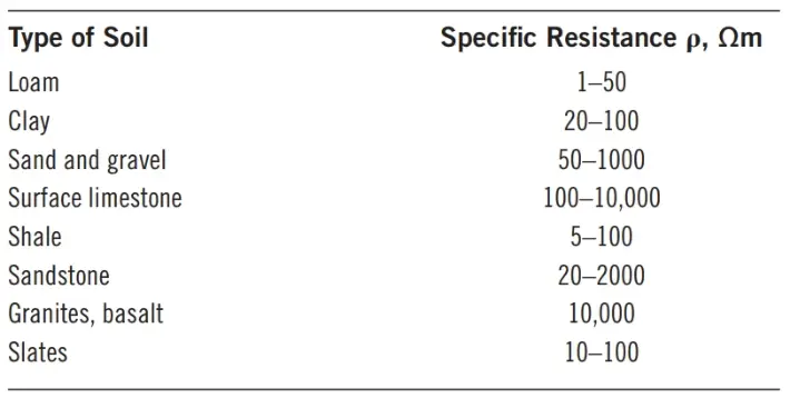
It is only when a fault happens that the connections to ground and the earth play their role in the currents that seek a path to follow. In such a case a high current is flowing in the ground wire of a grounded system. Table 1 shows the specific resistance of various earth materials.
Table 1: Specific Resistance (Resistivity) of Soil
For most electrical equipment, grounding is performed by a solid or bolt connection to ground, whereas for a system, such as the electric network, generators (like in all wind turbines), and in larger and expensive equipment, grounding can be either solidly or through a current limiting device (see Figure 1).
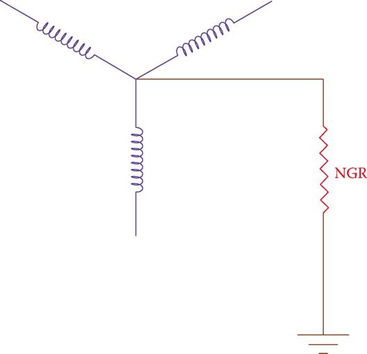
Figure 1 Neutral Grounding Resistor.
The purpose of a current limiting device is to reduce the current that will flow through a device, and a system or its parts in case of a fault, which can cause damage. A common current limiting device for this purpose is a neutral grounding resistance (NGR). Such a resistor, nonetheless, must be carefully selected based on a number of criteria including the involved voltage and the allowed delay for the protection device (e.g., a circuit breaker).
A low resistance neutral grounding or a high resistance neutral grounding can be employed. In the former, the allowed current is higher. A current of 50 A or more (up to 400 A) is allowed for 10 sec. In the latter, the maximum allowed current is 25 A for potentials of 600 V or less. A current of 5 A is more common. For higher voltages (13.8 kV and up), solid grounding is normally employed.
Neutral grounding resistance (NGR): An added resistance to the grounding strap to limit the (otherwise high) current flow through a device or a circuit in case of a fault.
Instead of directly connecting a grounding resistor to the ground bus, a single-phase transformer can be employed, as shown in Figure 2. In this case, a smaller resistor is used based on the transformer turns ratio.
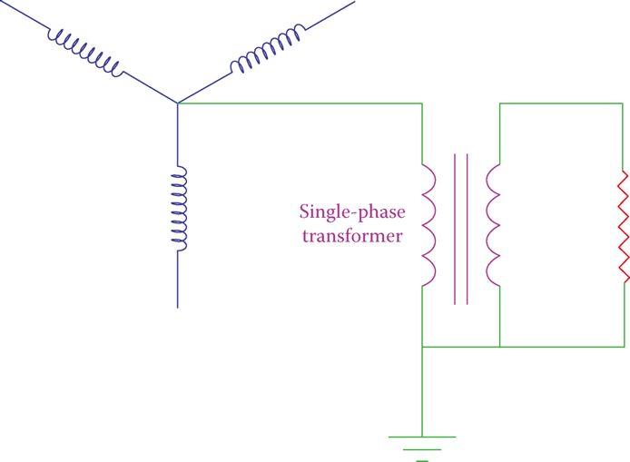
Figure 2 Using a single-phase transformer in conjunction with a grounding resistor.
It is important to have the grounding point on the secondary of a grounding transformer and as near to it as possible.
An inductor resists a change in the current through it. This property makes it a candidate for current limiting, so it is desirable for grounding. As another means for grounding, a reactor can be used.
A reactor is a winding (inductor) with or without a core, dry or oil immersed, which is specifically designed for a number of purposes, including grounding. Among other reactor, applications are inrush-current limiting (for capacitors and motors), harmonic filtering, reactive power compensation, reduction of ripple currents, damping of switching transients, flicker reduction, load balancing, and power conditioning.
Reactor: Wire winding with or without a core, dry or oil immersed, which is specifically designed for a number of purposes, including grounding in a three-phase system.
What Point Must Be Grounded?
So far, we have talked about grounding. But, what point must be grounded? The center point in a star connection of three-phase systems has a zero voltage with respect to all the phase lines. This point is, thus, a good reference for grounding. This is a point that, when it exists, it is grounded in all power facilities. When this point does not exist, in a delta connection, for example, such a point is created by an auxiliary transformer.
When this point is grounded in the source, and the loads have a similar point grounded, these points are connected to each other through the earth and any current coming from the load to ground finds its return way to the source through the earth. This can be a small current in the case of unbalanced three-phase loads or a high current in the case of a fault.
Remember that a substation is a load to a generator or to an upstream substation. In the same fashion, a substation is a source for the loads or for a downstream substation.
Grounding in Power Transmission
Three-phase transformers can be used in four different configurations. These are delta-delta, delta-wye, wye-delta, and wye-wye. Each of these combinations has its advantages and disadvantages.
A wye connection provides a suitable point for grounding. A delta connection provides a path for capturing third-order harmonics, which is quite important in power transmission and distribution.
It is more common to have one side delta connected and the other side wye connected to benefit from both advantages. However, it might be necessary to use a grounding transformer for the side with the delta connection.
The standard configuration by utilities for power transmission is “delta high – grounded wye low.” This implies that the higher voltage side is delta connected and the lower voltage side is star connected and it is grounded. This has the advantage that the low voltage bus has always a ground reference.
Moreover, the common practice in traditional power plants (thermal and hydraulic plants) is to have the generator step-up (GSU) transformer delta connected at the generator side (lower voltage) and the transformer secondary star-connected and grounded. A grounding transformer is then used for the generator to provide a solid ground for fault protection. This is depicted in Figure 3.
A grounding transformer must have the correct size and rating for its purpose. Thus, its selection must be based on a careful study, and it is an additional cost to any facility.
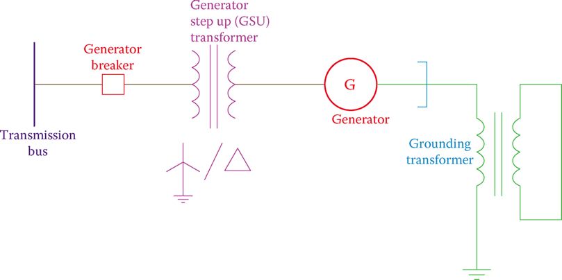
Figure 3 Common arrangement for generators in traditional power plants.
Grounding transformer: Transformer used only for providing a reference point for connection to ground, in order for detection of faults in power generation and distribution.
In wind farms, however, because there are many wind turbines in a wind farm, the transformer at the generator side is star connected and grounded and the collector side (high voltage) is delta connected.
The standard configuration by utilities for power transmission is “Delta high – grounded wye low.”
A grounding transformer is a special wye-delta transformer that is designed for this purpose only. The secondary is not connected to any load and the primary is connected to the three-phase line at the location the grounding is desired.
In the case of significant unbalance primary currents (a fault), very high currents circulate in the secondary windings. The transformer, therefore, must have been designed and rated for handling the high currents. Also, a zigzag transformer can be used for grounding.
A grounding transformer is a special wye-delta transformer with its secondary not connected to any load. It is designed for the purpose of grounding only.
Fault Detection in Transmission Lines Key Takeaways
The detection of faults and implementation of proper grounding techniques in transmission lines are not only critical for the safety and stability of power systems but also for ensuring uninterrupted electricity supply across industrial, commercial, and residential sectors. Grounding systems, neutral grounding resistors, reactors, and grounding transformers are essential components that help limit fault currents, prevent equipment damage, and protect human life. These protective measures play a vital role in maintaining power quality, minimizing downtime, and avoiding costly repairs or replacements. Their application is especially significant in high-voltage transmission networks, power plants, and renewable energy systems like wind farms, where system reliability and personnel safety are top priorities.