The article provides an overview of electric cable, focusing on the types, structure, and materials used in overhead and underground conductors, as well as their electrical and physical properties. It also explains key concepts such as resistance, ampacity, and specific resistance (resistivity), including how these values vary with temperature and conductor design.
Electric cables or conductors are basically of two types, but each type has numerous categories. Conductors are either for overhead transmission lines or for underground installation. Overhead conductors are bare wire and do not have insulation except at residential areas where contact with trees and other objects is possible, whereas underground conductors cannot be without insulation.
Overhead cables are cheaper because they do not have the problems with the inclusion of insulation material and the required properties in their manufacturing process. But, they must be mechanically stronger because they are suspended from the poles/towers, and they must support their own weight, for which they must withstand great tension. All conductors expand owing to heat generated in them when carrying current. This causes overhang conductors to sag more, which sometimes can result in contacts with lower lines or trees.
Overhead Conductors
For transmission lines nowadays, the conductors are made of aluminum. Compared with copper, aluminum has less conductivity and less strength. For this reason, for the same power transmission, aluminum conductors must be thicker. Also, for overhead lines, their strength can be reinforced by steel.
Theoretically, conductors can be made out of rigid bars. However, for transportation this is impossible and they should be flexible. See Figure 1. To increase the flexibility of thicker conductors, they are made of several strands. As the current carrying capacity requirement of electric cable increases, more strands are added, and accordingly, more reinforcement is necessary.
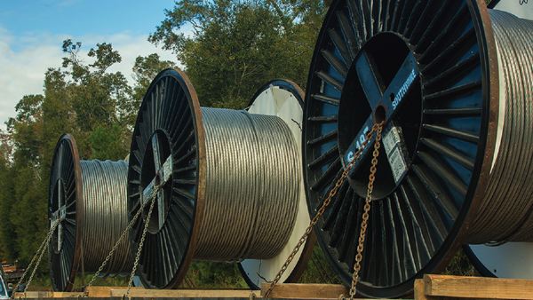
Figure 1 For various reasons including transportation, conductors must be flexible.
The customary number of strands in overhead cables is as follows:
1 – 7 – 19 – 37 – 61 – 91, and 127
Note that each layer has six strands more than the layer inside it. For example, 19 = 1 + 6 + (6 + 6) and 37 = 1 + 6 + 12 + (12 + 6), etc. See Figure 2.
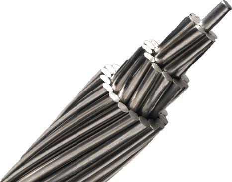
Figure 2 Typical bare wire conductor.
There are several categories of aluminum conductors. These are some of the more common aluminum conductors: all aluminum conductor (AAC), all aluminum alloy conductor (AAAC), aluminum conductor alloy reinforced (ACAR), aluminum conductor steel reinforced (ACSR), aluminum conductor steel supported (ACSS), aluminum conductor carbon fiber reinforced (ACFR), and gap-type aluminum conductor steel reinforced (GTACSR).
There are other categories as well. The names are self-explanatory, to some extent, but can change from company to company. Not all conductors have strands with circular cross-section. Figure 3 shows an electric cable with oval shape strands.
Also, to increase the conductivity of cables for the same cross-section, some cables have trapezoid shape strands that form circular layers, which resemble tubes of different diameters inside each other (see Figure 4). In this way, more use of space (thus, more conductivity) is made out of the same conductor diameter.
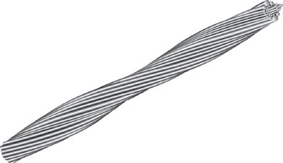
Figure 3 Conductor with oval cross section.
More recently, carbon fiber reinforcement cables have been introduced; instead of steel, these electric cables have strands of carbon fiber composite material in the middle. Carbon fiber composite cable (CFCC) offers desired properties such as less weight and smaller thermal expansion compared with steel. It has 1/5 of the weight and 1/12 of thermal expansion of those of steel, for a price. Figure 5 shows a picture of such a cable.
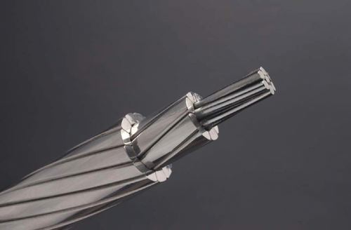
Figure 4 Conductor with trapezoid strands.
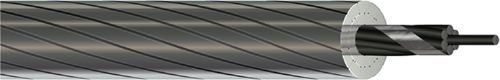
Figure 5 Aluminum conductor with a composite core.
A gap-type conductor consists of a core of high strength steel surrounded by a small gap filled with temperature resistant grease. Stacked around this gap are the trapezoid shape stands of aluminum.
In the seven-strand conductor, there are six aluminum strands around one steel cable. The number of steel strands depends on the specification of a particular conductor. For a 37-strand electric cable, there are 30 aluminum and 7 steel strands, but for the 61-strand cable the number of steel strands can be 7 or 19 and the rest are aluminum. There are always exceptions, and these depend on the manufacturer.
Electric poles and supporting structures come in different forms and sizes, mainly based on the voltage of the power they transmit. Some typical ones are shown in Figure 6. For the final distribution to consumers” poles of approximately 12 m (40 ft) are used, and the height of larger structures varies between 18 and 42 m (60 and 140 ft).
Electrical Properties of Electric Wires and Cables
The principal electrical property of a piece of metal is the resistance R that it shows to the flow of electrical current. It is very important to know the resistance of electric conductors when they are used in electric circuits.
Knowing R allows one to determine voltage drop and the energy transformed into heat in parts of an electric circuit, in motor windings, and so forth.
In addition to this property, for wires and cables, there is another property that determines how much current is allowed to pass through a conductor. This property, called ampacity (made from the two words “ampere” and “capacity”), defines the current capacity of a conductor based on the heat that is generated owing to electrical current, the structure, and material of the conductor, and ambient temperature.
It is easy to understand, therefore, that whereas the resistance of a wire can be almost constant, its ampacity depends on the temperature and some other working conditions, and it cannot be a constant.
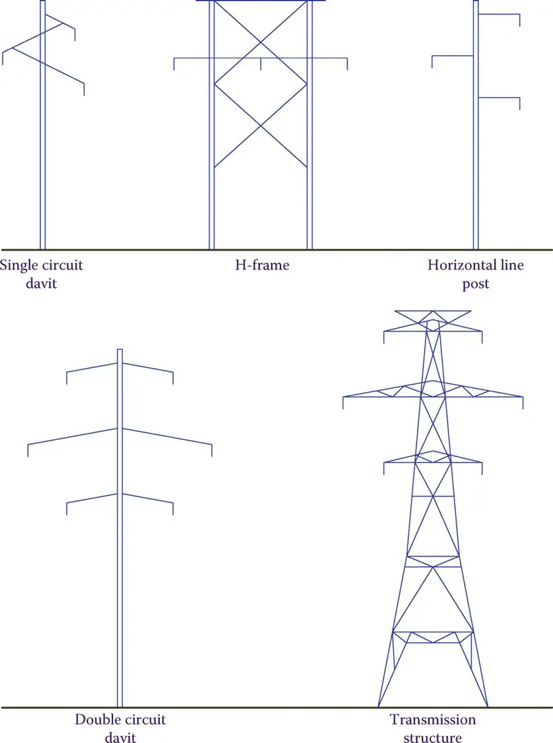
Figure 6 Various transmission line supports.
Ampacity: A word (name) made of Ampere and Capacity. It is used to define the current capacity of standard conductors (wires) in different working conditions for safe operation. Ampacity is determined based on the heat generated in a conductor due to the current through it.
The resistance of a piece of any material (even an insulator) to the flow of electricity is proportional to its length and inversely proportional to its cross-section area. So, for example, if the length of a wire doubles, its resistance doubles, but if cross section doubles, resistance halves.
R depends also on the material; for example, copper is a much better conductor than iron. This is why wires are made up of copper and not iron. The effect of the material is designated by the Greek letter ρ (rho, pronounced ro), which represents the resistance of a piece of the material with specific dimensions. The value ρ is called the specific resistance or resistivity of a substance.
Specific resistance: Same as resistivity: the electric resistance of a specific size (based on the measurement system) of a metal or material.
Resistivity: Same as specific resistance: the electric resistance of a specific size (based on the measurement system) of a metal or material.
On the basis of the aforementioned discussion, resistance R of a piece of wire can be found from
$R=\rho \frac{L}{A}$
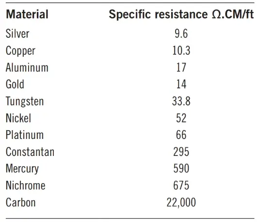
Where ρ is the specific resistance, l is the length, and A is the cross-section area of the wire. Table 1 shows the specific resistance of some metals and nonmetals in the metric system. The numbers shown are for the measurements made at 20°C. For other temperatures, values must be corrected by using the temperature coefficients in column 3 of Table 1.
Table 1: Specific Resistance (Resistivity) of Some Metals and Insulators

Table 1 also shows the conductivity of materials. Conductivity is the inverse of resistivity. It is an indicator of how conductive a material is. Its unit in the metric system is, thus, 1/ohm-meter. Also shown in the table is the temperature coefficient, which represents how much the specific resistance of a metal changes with temperature. This implies that ρ does not have a constant value.
Values given in tables are usually for the resistivity at room temperature (20°C). The relationship to calculate specific resistance of a metal at a different temperature than that known is
$\begin{matrix}{{\rho }_{2}}={{\rho }_{1}}\left[ 1+{{\alpha }_{1}}\left( {{t}_{2}}-{{t}_{1}} \right) \right] & {} & \left( 2 \right) \\\end{matrix}$
Where t2 is the temperature at which we need to know the specific resistance ρ2, t1 is the temperature at which the value is known (ρ1), α1 is the temperature coefficient at t1.
Temperature coefficient: Numerical value (positive for metals) representing how much the specific resistance of material changes with temperature.
Equation 2 can be readily substituted by
$\begin{matrix}{{R}_{2}}={{R}_{1}}\left[ 1+{{\alpha }_{1}}\left( {{t}_{2}}-{{t}_{1}} \right) \right] & {} & \left( 3 \right) \\\end{matrix}$
Where R1 is the known value of the resistance at t1 and R2 is the resistance at t2.
The variation of the temperature coefficient α can be found from
\[\begin{matrix}{{\alpha }_{1}}=\frac{{{\alpha }_{0}}}{1+{{\alpha }_{0}}{{t}_{1}}} & {} & \left( 4 \right) \\\end{matrix}\]
α0 is the temperature coefficient at zero degrees.
Specific Resistance
Specific resistance is the electrical resistance of a specific size of a material, and it is shown by the Greek letter ρ.
In the metric system, ρ is the resistance of a piece of metal (10 mm × 10 mm × 10 mm), that is 1 cm long and has a cross-section of 1 cm2 (see figure below).
Because in the metric system the units for the length and area are meter and square meter, respectively, ρ is defined in ohm-meter (Ω.m) so that when inserted in the relationship for resistance $R=\rho \frac{L}{A}$ the resultant is Ω.
\[\Omega .m\frac{m}{{{m}^{2}}}\to \Omega \]
In the US customary system, ρ is defined by the resistance of 1 foot of metal with a cross-section of 1 circular mil (CM). The unit of measurement for ρ, therefore, is ohm-circular mil per foot (Ω.CM/ft).
Circular mil: Unit for measuring the thickness (cross section) of wires. A CM is the area of a circle whose diameter is one mil (1/1000 of an inch).
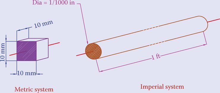
Figure 7 Circular Mill
Example 1
What is the resistance of a copper wire 50 m long and having a cross-section area of 16.78 mm2 (AWG 5 wire)?
Solution
The resistivity of copper is 1.6779 (10−8) ohm-m. Thus,
\[R=\rho \frac{L}{A}=1.6779\times {{10}^{-8}}\times \left( \frac{50}{16.78\times {{10}^{-6}}} \right)=0.05\Omega \]
Example 2
If the specific resistance of copper in the metric system is 1.6779 × 10⁻⁸ (Ω.m), find what is it in the imperial system (Ω.CM/ft).
Solution
We should calculate the resistance of a foot long (0.3048 m) of the cable with a diameter of 1 mil (1/1000 inch).
\[\begin{align}& Length=1ft=0.3048m \\& Diameter=1mil=0.001in=0.0000254m=25.4\times {{10}^{-6}}m \\& Area=\pi \frac{{{d}^{2}}}{4}=3.14\times \frac{{{\left( 25.4\times {{10}^{-6}} \right)}^{2}}}{4}=5.067\times {{10}^{-10}}{{m}^{2}} \\& R=\rho \frac{L}{A}=1.68\times {{10}^{-8}}\times \frac{0.3048}{5.067\times {{10}^{-10}}}=10.11\Omega \\\end{align}\]
Thus, the specific resistance of copper in the imperial system is 10.11 Ω.CM/ft.
In the above example, the number in the second bracket can be used for conversion between values of specific resistance in the metric system and in the imperial system. Note that in the above example and in Table 1, the specific resistance is (Ω.m) but sometimes it can be given in (Ω.cm).
Noting that
\[{{10}^{-8}}\times \frac{0.3048}{5.067\times {{10}^{-10}}}=6.0115\cong 6\]
Shows that when the specific resistance of a material in the metric system is given in Ω.m and in the form of a number multiplied by 10−8, we may easily find its value in Ω.CM/ft by multiplying the first number by 6.
Table 2 shows the specific resistance of a few metals in the imperial system of measurements.
Table 2 Resistivity of Some Metals in Ω.CM/ft
Example 3
The diameter of a lightbulb filament is 0.05 mm, and it is made out of tungsten with the specific resistance of 5.6 × 10⁻⁸ Ω.m at the room temperature. If the filament length is 5 cm, what is the resistance of the filament at the room temperature?
Solution
Length = 0.05 mm
Radius = 0.025 x 10⁻³ m
\[R=5.6\times {{10}^{-8}}\times \frac{0.05}{3.14\times {{\left( 0.025\times {{10}^{-3}} \right)}^{2}}}=1.426\Omega \]
Example 4
The resistance of a piece of wire 10 ft long is 100 mΩ. If the wire is made out of copper, find its thickness in CM.
Solution
The specific resistance of copper in the imperial system is 10.11 Ω.CM/ft. From Equation 1 it follows that
\[A=\frac{\rho l}{R}=\frac{10.11\times 10}{0.1}=1011CM\left( wire\text{ }thickness \right)\]
The diameter of the wire is
$\sqrt{1011}=31.8mil$
Example 5
A piece of tungsten wire has a circular cross-section with a diameter of 22 mils. What length of this metal makes a resistance of 10 Ω?
Solution
Diameter = 22 mil = 0.022 in = 0.0005588 m = 5.588 × 10⁻⁴ m
Cross-section area = \[3.14\times {{\left( \frac{5.588}{2}\times {{10}^{-4}} \right)}^{2}}=2.4525\times {{10}^{-7}}{{m}^{2}}\]
It follows from the resistance relationship that
\[l=\frac{RA}{\rho }=\frac{10\times 2.4525\times {{10}^{-7}}}{5.5\times {{10}^{-8}}}=44.6m\]
Length in English units = 44.6 × 3.28 = 146.3 ft
Example 6
If the resistance of a piece of tungsten wire at 20°C is 5 Ω, what is its resistance at 1200°C?
Solution
From Table 2 we see that the specific resistance and the temperature coefficient α for tungsten at 20°C are respectively 5.6 × 10⁻⁸ and 0.0045. Applying those in Equation 2 leads to
\[\begin{matrix}{{\rho }_{_{1200}}}=\text{ }5.6\text{ }\times \text{ }{{10}^{-8}}\left[ 1\text{ + }0.0045\text{ }\times \text{ }\left( 1200\text{ }\text{ }20 \right) \right] \\~~~~~~=\text{ }5.6\text{ }\times \text{ }6.31\text{ }\times \text{ }{{10}^{-8}}=\text{ }35.336\text{ }\times \text{ }{{10}^{-8}} \\\end{matrix}\]
The specific resistance is 6.31× larger. The resistance is, thus, larger by the same ratio. Therefore,
R1200 = (5) (6.31) = 31.55 Ω
You realize that when a light bulb is on, the temperature of the filament is much more than room temperature, and, therefore, the resistance of its filament is several times larger than when at room temperature.
The standard wire sizes are given in Table 3 for both aluminum and copper wires. Table 3 also indicates the electric resistance per 1000 m and 1000 ft of these wires. AWG stands for American wire gauge.
Table 3: American Wire Gauge Table


Insulated Conductors and Ampacity
Ampacity is determined based on the amount of heat generated in a conductor owing to the current and the fact that this heat must be taken away so that the conductor temperature does not increase anymore beyond a certain safe level. Otherwise, the buildup of heat can cause a problem.
In this sense, the ambient temperature and the nature of the conductor and its surroundings are the parameters that affect the ampacity rating of a conductor. In this respect, the same cable has more ampacity when in the air than when in a conduit.
Figure 8 illustrates a three-conductor underground electric cable. These cables come in different sizes with one, two, and three conductors and various insulation materials. Good electrical insulation is absolutely necessary for underground cables.
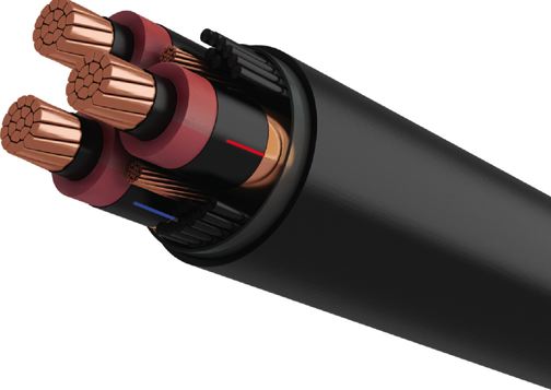
Figure 8 A three-conductor underground electric cable.
Overhead lines are normally in the air and cooled by streams of free air, whereas the underground cables are either in a conduit or buried underground. Also, their insulation decreases the rate of cooling compared to bare wires. The ambient temperature can be −30°C or +30°C, for instance, and it can vary significantly from winter to summer. Selection of electric cable must be based on the worst-case scenario and the highest ambient temperature.
Electric Cable Key Takeaways
Understanding the different types, materials, and electrical properties of electric cables is essential for their effective application in power transmission systems. The choice of electric cable—whether it is for overhead transmission lines or underground installation—depends on factors such as cost, strength, and environmental considerations. The physical properties of the cables, such as resistance, ampacity, and specific resistance, play a crucial role in determining their performance in various conditions. Electric cables made from materials like aluminum and copper are widely used, with different designs like multi-strand conductors and reinforced cores offering increased flexibility and strength. Additionally, the development of advanced electric cable designs, such as carbon fiber reinforcement, provides even better performance, particularly in areas that require lightweight and efficient solutions.