The article discusses the historical evolution, technical configuration, and operational principles of High-Voltage DC (HVDC) power transmission systems. It also outlines the key advantages and disadvantages of HVDC compared to AC systems, while considering their future potential, economic viability, and applications in modern power transmission.
Advantages and disadvantages of a High-Voltage DC power transmission system should be analyzed in detail. Only then can we raise the question: Is AC energy transmission the most efficient option for the 21st century?
AC energy transmission is the most common mode of energy transmission in the world. DC transmission can be found only in some specific applications. The advantages and disadvantages of High-Voltage DC energy transmission should be analyzed in detail. Only then can we raise the question: Is AC energy transmission the most efficient way for the 21st century?
Nowadays, requirements for increasing an efficiency and reliability of transmission, distribution, and consumption of electrical energy question the use of alternating current (AC) transmission system. Currently, intensive research of direct current (DC) systems is performed because more and more disadvantages of the AC voltage systems are becoming visible.
Historical Background of AC and DC Systems
The first electrical power system was built and tested at the end of the nineteenth century. In the beginning, the DC power systems were mostly used. The DC power transmission system had several limitations.
The DC voltage could not be transformed, thus the energy could not be transmitted to the long distance without high voltage drop value and power losses.
Thomas Alva Edison and his team developed the DC generator, circuit breaker equipment, fuses, bulbs and first DC systems in 1881. The DC systems operated with 110 volts as small isolated systems to decrease power losses.
Several years later (in 1887) George Westinghouse bought Tesla’s patents related to AC systems and employed him to continue its development.
The possibility of voltage transformation from one level to another made the AC system favorable for long-distance energy transmission. That was the main reason for surpassing DC energy systems. Nowadays the DC systems are used in some specific applications as telecommunication systems, vehicles, ships, tractions and high voltage transmission.
High-Voltage DC Power Transmission System Configuration
Essentially there are two main elements of high-voltage direct current (HVDC) system: converter stations at the endpoints of the transmission system and transmission lines (overhead lines, cables).
The converter stations are able to operate in both regimes as inverters or as rectifiers. This feature enables energy transmission in both directions.
The converter station is an innovative solution which basically enables HVDC system application. The most important parts of converter station are bridge converter unit and converter transformer. A semiconductor valve is the main component of bridge converter unit. An uncontrollable semiconductor valve is made of diodes while the controllable one is made of Thyristors connected in a series configuration.
High-performance Thyristors embedded in modern High-Voltage DC system have disk diameter ranging even up to 5 inches (125 mm) with the maximum current of 4 kA and blocking voltage capability above 8 kV.
The Thyristors can be connected in series configurations to get higher blocking capability with the voltages above 100 kV. Modern HVDC systems mostly use twelve-pulse bridge converters. They are designed as two fully controllable six-pulse bridge converters connected in a series configuration (Figure 1a).
A development of high-frequency components, such as IGBT, resulted in HV converters design which uses PWM (pulse width modulation) technology.
By using the PWM HV converters it is possible to regulate any frequency and amplitude by changing PWM signals. The main part of the PWM HV converter is IGBT bridge converter.
The modern IGBT has blocking voltage capability of 6.5 kV (the latest researching reaches over 8 kV), with the maximum current value of 3.6 kA and switching frequency from several tens kHz. These IGBT converters are resistant to the critical dv/dt value higher than 100 kV/µs (Figure 1b).
High-Voltage DC transformers are an important part of an HVDC system. They are employed to transform voltage from AC system to corresponding AC voltage value for bridge converter input.
The twelve-pulse bridge converter requires the supplying designed by two three-phase voltage systems shifted by 30°. This is accomplished by using two three-phase transformers (or the transformer with two secondary sides) with different winding configuration, one connected in Y-Y and the other in Y- Δ transformer vector group. This solution helps to cancel fifth and seventh harmonic from AC side and sixth harmonic from the DC side which results in significant saving in harmonics filters.
The converter stations contain other important equipment as AC filters, DC filter, surge arresters, disconnectors, etc.
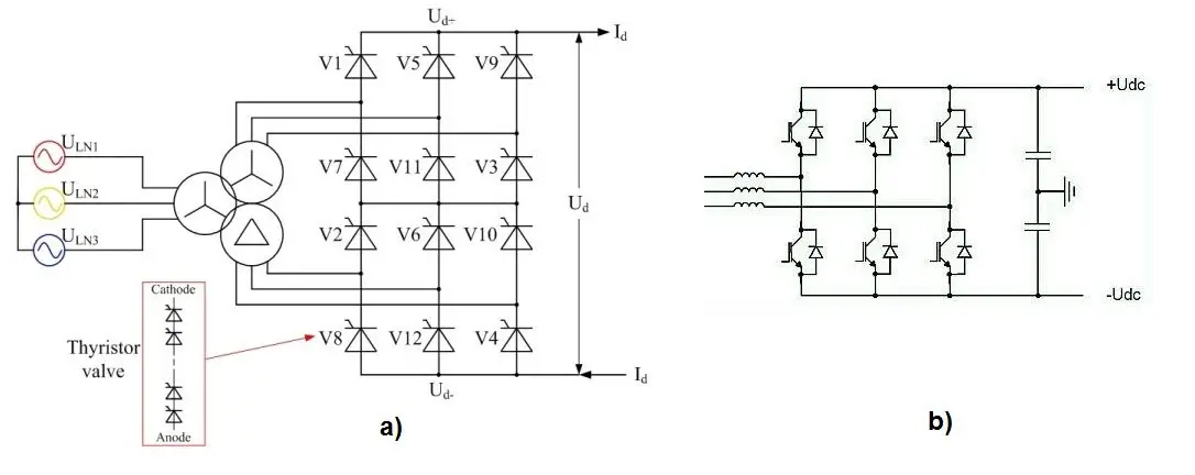
Figure 1. (a) Twelve-pulse bridge converter with two transformers secondary sides (Y-Y and Y-Δ) and (b) PWM HV converter.
Future of Power Transmission
A development of three-phase AC transmission system is approaching the limits of its possibilities. The limits are listed below:
- transmission power losses due to the inevitable reactive power transmission,
- increased power losses due to skin effect,
- the impossibility of interconnection ramified three-phase transmission systems with different nominal frequency (50-60 Hz) or with different frequency regulation method,
- increasing the short circuit current value (circuit breakers break faulty currents with difficulties, significant mechanical stress on electrical equipment),
- the impossibility of using longer cable’s lines (submarine) due to high transversal capacity value.
Because of those AC transmission system limitations, future of the energy transmission systems could be in new transmission technology based on using power electronics devices, known as High-Voltage DC transmission system.
Working principle of this system consists of AC power conversion into DC (by using rectifiers), long distance DC power transmission lines and DC power conversion into AC (by using inverters). The power conversion is performed in converter stations.
High-Voltage DC Transmission System Advantages:
- Decreased power losses, the influence of lines with parasitic inductance is insignificant,
- Almost full transmission capacity is used for active power transmission,
- A lower number of lines for transmitting the same amount of energy,
- A lower line cross section value (insignificant skin effect),
- A less expensive tower and transmission route due to a smaller number of lines (as illustrated in Figure 2),
- Submarine long-distance energy transmission due to low transversal capacity value.
- Because bipolar HVDC transmission lines require only two-pole conductors compared to three-phase conductors for AC systems, the HVDC system is economical when savings in conductor costs, losses, towers, and right-of-way costs offset the additional costs of converting equipment.
- The HVDC system has a greater flexibility of operation in that the transmission line may be operated in the monopolar mode with the ground return when one of the poles requires opening under a permanent faulted condition.
- Staging of facilities—connecting the Thyristors in series-parallel combinations—to accommodate desired voltage and current levels is another advantage of the DC system.
- Addition of a DC transmission line does not increase the short-circuit duty of the existing ac system.
- Control of converter Thyristors permits rapid changes in magnitude and direction of power flow and enhances system stability.
- An HVDC link may be used to interconnect two ac systems of different frequencies.
- The dc system has a relatively less reactive power flow problem.
- For a given power, its transmission at higher voltages is economical because of the reduced I2R losses.
- Radio interference for a dc system is less than that for an AC system.
High-Voltage DC Transmission System Disadvantages:
- Inverter operations produce a significant level of high harmonics in the network and ruin the power quality. Also, the power electronics produce noise in telecommunication signals. The encouraging fact is the development of filters which help decrease the influence of the disadvantages.
- The converter station consists of huge amount of thyristors which are expensive power electronic component. There are significant power losses during the thyristors operation.
- Also, it should not be forgotten that almost all electrical infrastructure and energy consumers are adapted to AC power.
Among the major problems associated with HVDC systems are ion drift during corona corrosion during monopolar operation with earth return, and complexity of the DC circuit breaker design. An HVDC system is considered economical only for transmission over distances exceeding 800 km. For overhead transmission along a distance of 600 to 1000 km, ±400 kV is considered an optimum voltage for a power level of 800 to 1000 MW. As the power increases, the optimum voltage also increases, such that ±1200 kV is the optimum for power levels ranging from 4000 to 10,000 MW.
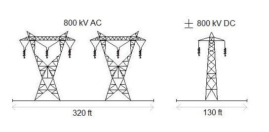
Figure 2. The HVDC transmission towers take up less space
High-Voltage DC Transmission Systems Economic Aspect
The cost-effectiveness of HVDC transmission system depends on several factors.
The main factor is transmission distance. In a case of shorter transmission distance, it is efficient to install High-Voltage AC transmission systems, while for the long-distance lines the High-Voltage VDC systems are cost-effective.
It is hard to find critical distance with which the HVDC system installation become justified. Just for the orientation purpose, the critical distance for overhead power transmission system is between 300 and 500 miles with transmission power of 2000 MW.
The cost of the HVDC system is high because of a converter station installation in the transmission system endpoints, while the cost of the HVAC system is significantly lower in those system parts.
The decision in favor of High-Voltage DC transmission system will be made in the following cases:
- When the HVDC transmission system is cost-effective compared to the three-phase HVAC system (high transmission power, long power transmission distance),
- When the HVAC system is not possible (interconnection of the asynchronous three-phase AC power network, long cable lines as submarine power transmission),
- When the power regulation and power flow control is required even if the HVAC transmission is cost-effective.
High-Voltage DC Power Transmission Key Takeaways
The importance of High-Voltage DC (HVDC) power transmission systems lies in their distinct technical and economic advantages, particularly in applications where traditional AC systems face limitations. HVDC technology enables efficient long-distance power transmission with reduced losses, smaller infrastructure footprint, and enhanced control over power flow. These benefits are especially crucial in scenarios such as intercontinental submarine cable links, interconnecting asynchronous power grids, and transmitting large amounts of power over vast distances. Although HVDC systems involve high initial investment and technical complexity, their growing adoption reflects a strategic shift towards more efficient and reliable energy transmission. As the global demand for clean and sustainable energy continues to rise, HVDC systems are poised to play a critical role in the modernization and expansion of future power networks.