The article provides an overview of protective relaying principles and their applications for high-voltage power system components. It covers the protection methods for generators, transformers, buses, and transmission lines using various relay types to detect and isolate faults efficiently.
The applications of the different types of protection systems for the protection of various types of equipment and transmission lines are described in this section. These discussions are confined to protection for the high-voltage, bulk-power system components.
Generator Protection
The protection system provided to the synchronous generator must be able to detect any abnormal condition immediately and act quickly to prevent damage to the generator and minimize the effect on the power system.
Synchronous generators are provided with protection against various disturbances, including short circuits in the stator windings, loss of field excitation, stator and rotor overheating, and over-speed. Short-circuit protection of the stator windings is of primary concern and is discussed in this section.
When a short circuit occurs between stator windings of a synchronous generator, or between a stator winding and ground, the protection system should quickly trip the main circuit breaker to disconnect the machine from the rest of the system and at the same time disconnect the field winding from the exciter.
The best stator winding short-circuit protection is provided by a percentage-differential relay, which is shown in Fig. 1. It may be noted that the relaying protects against a three-phase fault, or line-to-line fault, in the stator windings.

Figure 1 Generator Protection
When the synchronous generator neutral is grounded through a high resistance, the short-circuit current for a single line-to-ground fault is much less than the short-circuit currents for faults involving the phase windings. Thus, the ground fault current may not be detected by the differential relaying protection.
An overvoltage relay connected across the grounding resistor would be able to detect the increased voltage across the resistor in the presence of a ground fault, and the overvoltage relay will operate.
Transformer Protection
The protection system provided for a power transformer depends primarily on its capacity and its voltage rating. Thus, for small transformers with capacities up to about 2 MVA, power fuses are deemed to be adequate.
For larger transformers, with capacities greater than 10 MVA, percentage-differential relays with harmonic restraint are recommended.
The one-line diagram of the protection of a three-winding transformer using a three- winding percentage-differential relay is illustrated in Fig. 2.
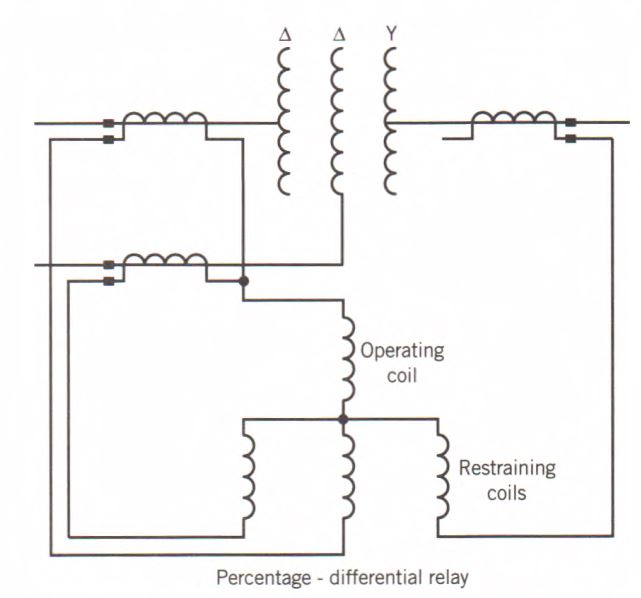
Figure 2 Three-winding transformer protection.
The differential relaying protection must satisfy two basic requirements:
- The protection must not operate for normal load conditions and faults external to the transformer.
- The relays must operate to trip the circuit breakers for an internal fault that is severe enough to cause direct damage to the transformer.
Three-phase transformers with Y-∆-connected windings require further consideration. The primary and secondary currents of such transformers normally differ not only in magnitude but also in phase angles because of the inherent phase shifts in Y-∆ or ∆-Y connections. The current transformers must, therefore, be connected in such a manner that the CT secondary line currents as seen by the protective relays are equal under normal operating conditions or for external faults.
The correct magnitude relationship is obtained by the proper choice of CT ratios and, if necessary, the use of an autotransformer in the CT secondary circuit.
The correct phase-angle relationship is obtained by connecting the CTs on the wye-connected side of the transformer in the delta and the CTs on the delta-connected side in wye.
In this way, the CT connections are able to compensate for the phase shift introduced by the Y-∆ or ∆-Y connection.
The design of the protection for a ∆-Y transformer using percentage-differential relays is illustrated in Fig. 3 and the following example.
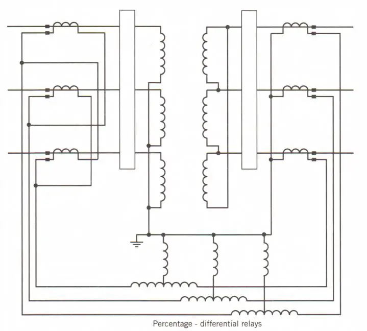
Figure 3 Y-∆ transformer protection
Example 1
Design the protection of a three-phase, 50-MVA, 230/34.5-kV power transformer using available standard CT ratios. The high-voltage side is Y connected and the low-voltage side is ∆ connected. Specify the CT ratios, and show the three-phase wiring diagram indicating the CT polarities. Determine the currents in the transformer and the CTs. Specify the rating of an autotransformer, if one is needed.
Solution
When the transformer is carrying the rated load, the line currents on the high-voltage side and low-voltage side are
$\begin{align} & {{I}_{HV}}=\frac{50000}{\sqrt{3}\times 230}=125.5A \\ & {{I}_{LV}}=\frac{50000}{\sqrt{3}\times 34.5}=836.7A \\\end{align}$
The CTs on the low-voltage side are connected in wye, and the CT ratio selected for this side is 900/5. The current in the leads flowing to the percentage- differential relay on this side is equal to the CT secondary current and is given by
${{I}_{LV,lead}}=836.7\left( \frac{5}{900} \right)=4.65A$
The current in the leads to the relay from the low-voltage side must be balanced by an equal current in the leads connected to the A-connected CTs on the high-voltage side. This requires a CT secondary current equal to
$\text{CT Ratio}=\frac{125.5}{2.68}=46.8$
The nearest available standard CT ratio is 250/5. If this CT ratio is selected, the CT secondary currents will actually be
${{I}_{CT,\sec }}=125.5\left( \frac{5}{250} \right)=2.51A$
Therefore, the currents in the leads to the ∆-connected CTs from the percentage- differential relays will be
${{I}_{HV,lead}}=\sqrt{3}\times 2.51=4.35A$
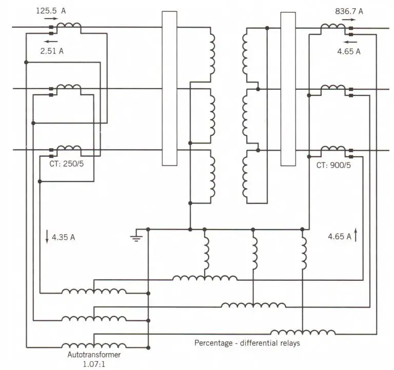
Figure 4 Y-∆ transformer protection of Example 1.
It is seen that the currents in the leads on both sides of the percentage- differential relay are not balanced. This condition cannot just be ignored because it could lead to improper tripping of the circuit breaker for an external fault. This problem can be solved by using an autotransformer as shown in Fig. 4. The autotransformer should have a turns ratio of
${{N}_{autotransformer}}=\frac{4.65}{4.35}=1.07$
In the design of the transformer protection of Example 1, the magnetizing current of the transformer has been assumed to be negligible. This is a reasonable assumption during normal operating conditions because the magnetizing current is a small percentage of the rated load current.
However, when a transformer is being energized, it may draw a large magnetizing inrush current that soon decays with time to its normal value. The inrush current flows only in the primary, causing an unbalance in current, and the differential relay will interpret this as an internal fault and will pick up to trip the circuit breakers.
To prevent the protection system from operating and tripping the transformer during its energization, percentage-differential relaying with harmonic restraint is recommended. This is based on the fact that the magnetizing inrush current has high harmonic content, whereas the fault current consists mainly of fundamental frequency sinusoid.
Thus, the current supplied to the restraining coil consists of the fundamental and harmonic components of the normal restraining current of (IA + IB)/2, plus another signal proportional to the harmonic content of the differential current (IA – IB)/2. Only the fundamental frequency of the differential current is supplied to the operating coil of the relay.
Bus Protection
The sum of the currents flowing through the lines connected to the same bus is equal to zero for normal operating conditions or for a fault external to the bus. Hence, differential relaying using overcurrent relays can be used to provide protection against bus faults. This is illustrated in the one-line diagram shown in Fig. 5.
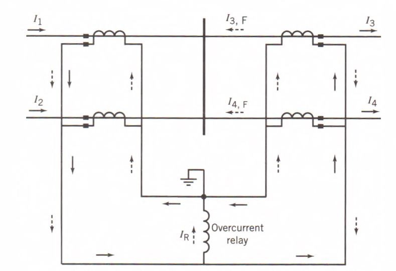
Figure 5 Bus Protection using an Overcurrent Relay
All of the current transformers are connected in parallel and an overcurrent relay is connected across their output. When there is no fault on the bus, the line currents are indicated by the solid arrows, and the current through the overcurrent relay is given by
${{I}_{R}}=\frac{1}{\text{CT Ratio}}\left( {{I}_{1}}+{{I}_{2}}-{{I}_{3}}-{{I}_{4}} \right)>0$
Therefore, no current flows through the relay. On the other hand, when there is a fault at the bus, currents I3 and I4 reverse directions as shown by the broken arrows; thus, the current through the relay is now given by
${{I}_{R}}=\frac{1}{\text{CT Ratio}}\left( {{I}_{1}}+{{I}_{2}}+{{I}_{3}}+{{I}_{4}} \right)>0$
Transmission Line Protection
Transmission lines provide the means for bringing the electric energy from the generating plants to the major substations, from these substations to the load center substations, and ultimately to the individual consumers.
Transmission lines travel over wide-open spaces, as well as thickly populated metropolitan areas. Because of these long distances and extensive exposure to nature and human accidents, most of the short circuits that occur in power systems are on overhead transmission and distribution lines.
For the low-voltage distribution circuits, the protection system usually provided consists of circuit reclosers and power fuses that act as relays and circuit breakers combined.
For the protection of medium-voltage and high-voltage transmission lines, separate relays and circuit breakers are employed. Since HV and EHV transmission lines are the major means of bulk-power transmission, the protection of these transmission lines is designed to be more reliable and more selective, and it is also more expensive.
Transmission Line Protection by Overcurrent Relays
Consider that the portion of the power system to be protected is radial as shown in Fig. 6. The generator connected to bus 1 represents the rest of the power system, and it supplies loads at buses 1, 2, 3, 4, and 5 through four transmission lines.
Since the short-circuit current comes from the left side of each line, it is sufficient to provide only one circuit breaker at the sending end for each line. So that service disruption is minimized, for a fault on line 4-5, only circuit breaker CB4 should be tripped; for a fault on the line 3-4, only breaker CB3 should be opened; for a fault on the line 2-3, only CB2 should be tripped; and so on.
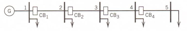
Figure 6 Radial Power System
The short-circuit current due to a fault on any of the lines depends on the fault location and the type of fault. Since the total impedance increases with the distance from the generator to the fault, the short-circuit current is inversely proportional to this distance.
Overcurrent relays are used mainly to provide protection for sub-transmission and distribution lines. Two forms of overcurrent protection are provided: primary protection for the line itself and backup protection for an adjacent line. Two types of overcurrent relay units are used: time overcurrent relay and instantaneous relay.
The time overcurrent relays at each of the four buses 1, 2, 3, and 4 provide primary protection for their own line segment and provide remote backup protection to adjacent line downstream from the relay location. Thus, the relay at bus 1 provides primary’ protection for line 1-2 and also provides backup protection for line 2-3; the relay at bus 2 provides primary protection for line 2-3 and backup protection for line 3-4; and so forth.
When the relay at bus 1 provides backup protection for line 2-3, it must be adjusted to be selective with the primary relaying at bus 2. The relay at bus 2 is expected to operate first for a fault on line 2-3 before the relay at bus 1 operates.
The operating times of the relays at the different buses are shown in Fig. 7. Thus, for the fault shown, the relay at bus 4 picks up to trip circuit breaker CB4. If CB4 fails to open for any reason, the fault current persists, and after a certain time delay the relay at bus 3 picks up to trip CB3.
The relay at bus 2 is selective with the relay at bus 3; thus, if both CB3 and CB4 failed to open, the relay at bus 2 would pick up and trip CB2 after a long time delay.
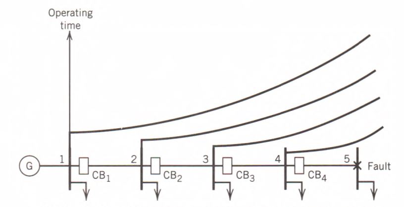
Figure 7 Overcurrent Protection of Radial Power System
For setting the pickup values and the selectivity clearances between the time overcurrent relays for backup protection, there are four criteria to consider:
- The relay must be able to pick up for the minimum short-circuit currents for which the relay is designed to protect.
- The relay should not pick up for normal load conditions. A common practice is to set the minimum pickup value equal to twice the peak load current in order to carry emergency peak loads and pick up the cold load.
- The relay nearer the source providing backup protection for the downstream relay must pick up to one-third of the minimum current seen by the latter.
- The relay nearer the source providing backup protection for the downstream relay should pick up for the maximum current seen by the latter but no sooner than (a selectivity clearance of) at least 0.3 s.
The instantaneous overcurrent relay unit provides primary protection for its own protected line segment to supplement the time-delay overcurrent relay unit.
The instantaneous unit operates quickly with no intentional time delay, so it should be adjusted such that it does not operate for a fault on neighboring lines.
The pickup value is usually adjusted so that the instantaneous relay is able to detect a fault occurring at a distance of up to 80% of the line segment. The operating times of the instantaneous relay and the time-delay units are shown in Fig. 8.
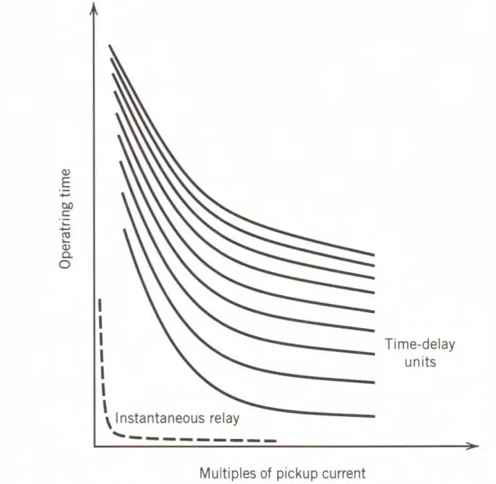
Figure 8 Typical time characteristics of an overcurrent relay.
The complete protection system for a line consists of three overcurrent relays for phase fault protection and one overcurrent relay for ground fault protection. This protection system is shown in Fig. 9.
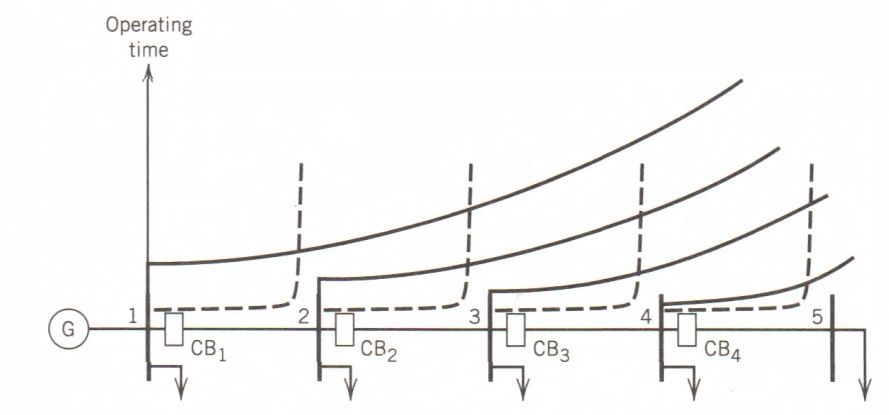
Figure 9 Complete overcurrent protection of a radial system.
Transmission Line Protection by Distance Relays
To improve reliability, the generating plants, transmission lines, and substations of a high-voltage power system are interconnected to form a network.
Overcurrent relay protection can no longer be used because coordinating the relays becomes a difficult, if not impossible, task.
Protection of transmission lines connected as a network can be provided by distance relays. These distance relays provide phase fault protection for the line, while an overcurrent relay provides ground fault protection.
Distance relays provide primary protection for a line section and backup protection for an adjacent line.
The value of impedance at the farthest fault location for which a distance relay picks up is called its “reach.”
One distance relay contains three distance relay units responding to three independently adjustable pickup impedance values (or zones of protection) with three independently adjustable time delays.
The primary impedance corresponding to a particular fault location, or relay unit reach, is converted to a secondary value that is used to adjust the phase or ground distance relay. This secondary impedance value is given by
${{Z}_{\sec }}={{Z}_{pri}}\left( \frac{CT\text{ }Ratio}{PT\text{ }Ratio} \right)$
The first-zone, or high-speed zone, unit of the distance relay has a reach of up to 80% to 90% of the length of the transmission line. This relay unit operates with no time delay.
The second-zone unit of the distance relay provides protection for the rest of the line beyond the reach of the first-zone unit.
This second-zone unit has a reach of at least 20% of the adjoining line section. Because this unit “sees” faults in the adjoining line, it must be selective with the first-zone unit of the adjacent line. Therefore, this second-zone unit is provided with a time delay of about 0.2 s to 0.5 s.
The third-zone unit of the distance relay provides backup protection for the rest of the adjoining line section. This unit is adjusted to reach beyond the end of the adjoining line to ensure that backup protection is provided for the full line section. The time delay provided for this unit is usually about 0.4 s to 1.0 s.
The protection of a portion of a power system by using distance relays is illustrated in Fig. 10.
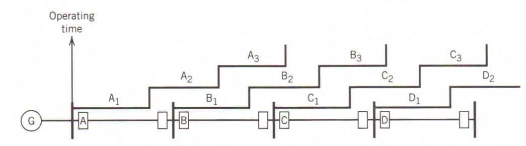
Figure 10 Line protection by distance relays.
Protective Relaying Key Takeaways
Protective relaying plays a vital role in ensuring the safety, stability, and reliability of high-voltage power systems. Its application in generator protection allows for rapid detection and isolation of internal faults, thereby preventing costly damage and reducing system disturbances. Similarly, transformer protection using percentage-differential relays with harmonic restraint ensures accurate fault detection while avoiding false tripping during inrush conditions. Bus protection through differential relaying provides dependable fault clearance within complex switching arrangements, and protective relaying systems applied to transmission lines safeguard the most exposed components of the power grid from frequent faults. Overall, protective relaying is essential for maintaining uninterrupted power delivery, minimizing equipment damage, and enabling efficient fault management across the entire electrical network. The strategic application of protective relaying across generators, transformers, buses, and transmission lines enhances the robustness and operational security of modern power systems, highlighting its irreplaceable value in real-world utility and industrial applications.