The National Electrical Code (NEC) defines “ground” as “A conducting connection, whether intentional or accidental, between an electrical circuit or equipment and the earth or to some conducting body that serves in place of the earth.”
Single-Phase Grounding
The grounding of a typical residential, single-phase service is represented in Figure 1. The local utility typically installs a transformer near a group of homes and extends 120/240 VAC electrical power to each house.
The utility would be responsible for the service up to the and including the meter. Beyond the meter, the wiring installation becomes the responsibility of the installer of the electrical system and the homeowner. Nevertheless, the utility might impose specific requirements for circuit protection within the building’s electrical panel.
The schematic representation of Figure 1 shows a typical electric panel that would house the circuit protective devices. The utility will commonly require a specific type of circuit protection for the two incoming live conductors.
Branch circuits within the building today are mostly protected with circuit breakers. Years ago, branch circuit protection was accomplished with fuses.
A neutral conductor at an installation will extend from the local transformer to the ground bar within the electrical panel. In the past, the neutral conductor has been bare, although today most neutral conductors are mostly insulated.
According to the latest edition of the NEC, 120 VAC branch circuits must consist of a live conductor, a neutral conductor, and a ground wire. The neutral conductor must be insulated, and the ground wire may be and usually is, uninsulated. (In the illustration of Figure 1, the live conductors would be the red phase and the black phase.)
The representation of Figure 1 shows a 120 VAC circuit extended to a lighting fixture. The circuit is extended from the red phase to a light switch. The light switch controls the light. A neutral conductor of the branch circuit connects to the ground bar in the panel. A ground wire, which is part of the branch circuit, connects to the metal of the lighting fixture.
Often the ground for a residence is a rod outside the house that had been driven deep into the ground. In the past years, grounding to a water pipe was allowed and is common in many older installations. However, the increasing use of plastic piping would present a problem if a ground were connected to water piping. For this reason, recent codes disallow using water piping as a ground source.
Unless both the red phase and the black phase have identical electrical loads, there would normally be a current flow through the grounding electrode to ground. So, a dependable ground, other than the building’s water piping, is a necessity.
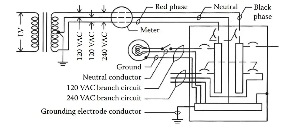
FIGURE 1: Single-phase service.
Should a short fault develop in the installation represented in Figure 1, a current would flow to the ground through the shortest path.
A typical ground fault occurring in a branch circuit of the red phase is shown in Figure 2. As shown, the current going to the ground would return to the local transformer through the two grounds that had been made available: one at the residence and one at the transformer.
The largest share of the fault current would go to the building’s ground since that would in most cases be the nearest ground connection. When the fault current rises to the setting of the circuit protective device, the current flow would be interrupted and the circuit deactivated.
Here, a line-to-ground fault is treated. Of course, another possible fault would involve a line-to-line short. Line-to-line faults are less common and present less potential for injury or property loss. Nevertheless, circuit protective devices must be capable of preventing an overcurrent condition resulting from a line-to-line short.
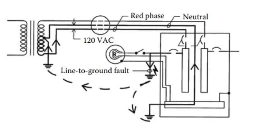
FIGURE 2: Single-phase line to ground fault.
Three-Phase Grounding
The grounding of three-phase circuits at the facility of a user of electric power may have a different appearance from that of the utility’s grounding practices. In any event, good grounding practices are always warranted. Three-phase grounding follows many of the principles applicable to single-phase circuits.
A typical three-phase four-wire service to a three-phase panel is represented in Figure 3. The four-wire service in the example of Figure 3 by definition has four conductors: phase A (represented as conductor “A”), phase B (represented as conductor “B”), phase C (represented as conductor “C”), and the neutral conductor (represented as conductor “N”).
A branch circuit consisting of conductors A, B, and C are extended to a wye wound motor. An equipment grounding conductor is likewise extended to the motor and connects to the motor frame. Operation of the motor depicted in Figure 3 is controlled by a motor starter.
As is the case with a single-phase electrical panel, a ground bar is provided within the panel for connections to the neutral conductors, the equipment grounding conductors, and the grounding electrode conductor.
The NEC standard requires that the resistance to the ground must be no greater than 25 Ω. However, many engineers consider a much lower resistance necessary whenever large currents are involved. A resistance in the range of 0.1–1.0 Ω, or lower, is considered a more practical value.

FIGURE 3: Three-phase service.
The current path resulting from a typical ground fault in a three-phase circuit is represented in Figure 4. As represented in Figure 4, the ground fault is assumed to be from the B phase of Figure 3 to the ground. Current would flow through the short to the ground, back to the panel ground bar, to the neutral conductor, and back to the respective transformer.
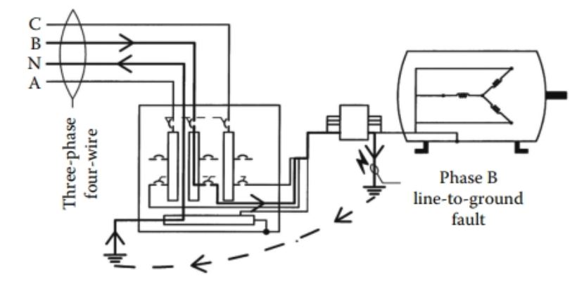
FIGURE 4: Three-phase line to ground fault.
Grounding Resistors
Electrical power, single-phase or three-phase, supplied to a user as a residence or a commercial building is generally grounded with a “solid ground” connection.
A solid ground would typically be a conductor that connects to a ground source as a ground rod, a ground mat, or, as was common in the past, merely underground water pipes. Solid ground connections are shown in Figures 3 through 4.
The purpose of the grounding electrode conductor is to minimize resistance to the flow of electrical current to the ground source.
In other words, the grounding electrode conductor should be of a low resistance. On the other hand, industrial power distribution facilities involving large transformers, generators, large motors, and some other types of electrical gear are often fitted with a resistor of one type or another in the ground path.
According to the IEEE standards, the reasons for limiting the current by resistance grounding may be one or more of the following:
- To reduce burning and melting effects in faulted electrical equipment such as switchgear, transformers, cables, and rotating machines
- To reduce mechanical stresses in circuits and apparatus carrying fault currents
- To reduce electrical-shock hazards to personnel caused by stray ground fault currents in the ground return path
- To reduce the arc blast or flash hazard to personnel who may have accidentally caused or who happen to be in close proximity to the ground fault
- To reduce the momentary line-voltage dip occasioned by the occurrence and clearing of a ground fault
- To secure control of the transient overvoltages while at the same time avoiding the shutdown of a facility circuit on the occurrence of the first ground fault (high-resistance grounding)
Ground Fault Detector
Ground fault detectors are commonly used with ungrounded and high-resistance ground (HGR) systems. A ground fault detector typically has a CT through which all of the circuit’s power conductors pass. The CT may be remote from the detector or the CT could be integral to the device.
Under normal conditions, the three-phase currents balance one another, and the ground fault detector does not detect a discrepancy. In the event of a short to ground, the sensed currents would become unbalanced, and the ground fault detector would detect the difference.
In some circuits, a ground fault detector is used merely to initiate an alarm in the event of a ground fault condition without any action to bring about deactivation of the circuit.
In other instances, a ground fault detector can be used to directly initiate action to deactivate the respective circuit. Applicable codes in some instances require ground fault detectors to deactivate circuits.
More specifically, ground fault detectors are required by some codes for mine electrical installations and for some portable equipment. A typical circuit employing a ground fault detector and an HGR is represented in Figure 5.
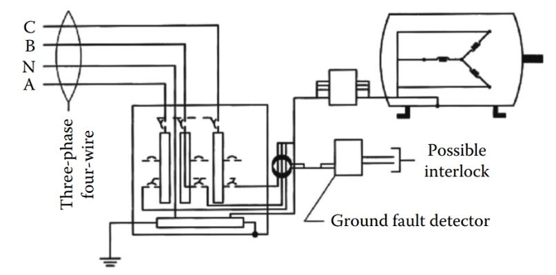
FIGURE 5: Ground fault detector and HGR.
Neutral Grounding Reactor
On larger generators and transformers, it is common to use a neutral grounding reactor in lieu of either a neutral ground resistor or a high ground resistor to limit ground fault currents.
Unlike a neutral ground resistor or a high ground resistor that offer resistance to current flow by means of resistive elements, a neutral ground reactor resists current flow with inductive elements.
A neutral ground reactor consists of coils, wound around either an air core or an iron core. A neutral ground reactor is wired between the circuit neutral and ground as represented in Figure 6.
During normal operation current, flow through the reactor to the ground is nil. With a balanced condition, current flow would be zero; under an unbalanced network condition, current flow would be slight due to the elevation of the network neutral.
Much as a neutral ground resistor or a high ground resistor, a neutral ground reactor greatly reduces stress on equipment that would otherwise result from the high currents of a ground fault.
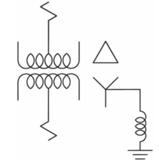 FIGURE 6: Neutral grounding reactor.