The article discusses various types of faults in power systems, focusing on both symmetrical and unsymmetrical faults and their impact on system stability and protection. It also covers fault analysis methods, including sequence networks and calculations essential for designing effective protection schemes and ensuring transient stability.
The normal operation of the power system at steady state is affected, sometimes dramatically, by the occurrence of such disturbances as overloads and short circuits. Of primary concern are short circuits, not only because they can cause large damage to the affected system component but also because they may lead to instability of the whole power system. Thus, there is a need to design protection schemes to minimize the risks involved with the occurrences of disturbances.
Fault analysis forms the basis for designing such protection systems. The proper coordination of the protective relays and the correct specification of circuit breaker ratings are based on the results of fault calculations. The performance of the power system is simulated in what is called transient stability analysis under a variety of disturbances, such as short circuits, sudden large load changes, and switching operations.
Power system protection is an important concern because short circuits present danger of damage to the equipment and loss of synchronism of the synchronous machines. The different types of protection systems and their applications for protecting the various power system components are discussed in the third section of this chapter.
Transient stability studies investigate the ability of the power system to remain in synchronism during major disturbances, such as equipment failure, major load changes, or momentary faults. Basic stability concepts are presented in the last section, along with a brief description of the models for generators, excitation systems, and governor-turbine systems.
Fault Analysis
The normal mode of operation of a power system is balanced three-phase AC. However, there are undesirable but unavoidable incidents that may temporarily disrupt normal conditions, as when the insulation of the system fails at any point or when a conducting material comes in contact with a bare conductor. Then we say a fault has occurred. A fault may be caused by lightning, trees falling on the electric wires, vehicular collision with the poles or towers, vandalism, and so forth.
Faults may be classified into four types. The different types of fault are listed here in the order of the frequency of their occurrence.
- Single line-to-ground fault (SLG)
- Line-to-line fault (L-L)
- Double line-to-ground fault (2LG)
- Balanced three-phase fault
Fault calculations provide information on currents and voltages in a power system during fault conditions. Short-circuit currents are computed for each relay and circuit breaker location and for various system contingency conditions, such as lines or generating units out of service, in order to determine the minimum and maximum fault currents. This information is useful to the engineer in selecting circuit breakers for fault interruption, selecting relays for fault detection, and determining the relay settings, which is referred to as relay coordination. The proper selection and setting of protective devices ensure minimum disruption of electrical service and limit possible damage to the faulted equipment.
Three-Phase Fault Analysis
Sufficient accuracy in fault studies can be obtained with certain simplifications in the model of the power system. These assumptions include the following:
- Shunt elements in the transformer model are neglected; that is, magnetizing currents and core losses are omitted.
- Shunt capacitances in the transmission line model are neglected.
- Transformers are set at nominal tap positions.
- All internal voltage sources are set equal to 1.0∠0°. This is equivalent to neglecting pre-fault load currents.
Three-phase fault calculations can be performed on a per-phase basis because the power system remains effectively balanced, or symmetrical, during a three-phase fault. Thus, the various power system components are represented by single-phase equivalent circuits wherein all three-phase connections are assumed to be converted to their equivalent wye connections. Calculations are performed using impedances per phase, phase currents, and line-to-neutral voltages.
Fault analysis, like any other power system calculation, is more conveniently performed using per-unit representation. The power system components are described in terms of their per-unit impedances or per-unit admittances.
The power base is selected and is used for all parts of the power system. The voltage bases are different for various parts of the system, and they are selected so that the per-unit turns ratio of the transformers is equal to unity. The current base and the impedance base are computed using the specified power base and voltage bases.
Single Line-to-Ground Fault
A single line-to-ground (SLG) fault is the most commonly occurring unsymmetrical fault. It may be caused by a vehicular accident causing one of the phase conductors to fall and come in contact with the earth, or it may be caused by tree branches, or it could be caused by flashovers across dusty insulators during rain-showers. A single line-to-ground fault is illustrated in Fig. 1.
Assuming that pre-fault currents are negligible, the SLG fault is described by the following voltage and current relationships.
$\begin{matrix} {{V}_{a}}=0 & {} & \left( 1 \right) \\\end{matrix}$
$\begin{matrix} {{I}_{b}}={{I}_{c}}=0 & {} & \left( 2 \right) \\\end{matrix}$
The sequence components of the short-circuit current are found by using following equation. Thus,
\[\begin{matrix} \left[ \begin{matrix} {{I}_{a0}} \\ {{I}_{a1}} \\ {{I}_{a2}} \\\end{matrix} \right]=\frac{1}{3}\left[ \begin{matrix} 1 & 1 & 1 \\ 1 & a & {{a}^{2}} \\ 1 & {{a}^{2}} & a \\\end{matrix} \right]\left[ \begin{matrix} {{I}_{a}} \\ 0 \\ 0 \\\end{matrix} \right] & {} & \left( 3 \right) \\\end{matrix}\]
Therefore, it is seen that the sequence components of the current are all equal to each other; that is,
$\begin{matrix} {{I}_{a0}}={{I}_{a1}}={{I}_{a2}}=\frac{1}{3}{{I}_{a}} & {} & \left( 4 \right) \\\end{matrix}$
The voltage of the principal phase a may be expressed in terms of its sequence components as
$\begin{matrix} {{V}_{a}}={{V}_{a0}}+{{V}_{a1}}+{{V}_{a2}}=0 & {} & \left( 5 \right) \\\end{matrix}$
By applying KVL to figure 2, we can obtain the following equation:
$\begin{matrix} {{E}_{a1}}-{{I}_{a1}}\left( {{Z}_{1}}+{{Z}_{2}}+{{Z}_{o}} \right)=0 & {} & \left( 6 \right) \\\end{matrix}$
The expression for Ia1 is obtained from Eq. 6, and using Eq. 4 provides the expressions for Ia2 and Ia0 as follows:
\[\begin{matrix} {{I}_{a1}}=\frac{{{E}_{a1}}}{{{Z}_{1}}+{{Z}_{2}}+{{Z}_{0}}}={{I}_{a2}}={{I}_{a0}} & {} & \left( 7 \right) \\\end{matrix}\]
The short-circuit current Ia is found as the sum of its sequence components; thus,
\[\begin{matrix} {{I}_{a}}={{I}_{a0}}+{{I}_{a1}}+{{I}_{a2}}=3\frac{{{E}_{a1}}}{{{Z}_{1}}+{{Z}_{2}}+{{Z}_{0}}} & {} & \left( 8 \right) \\\end{matrix}\]
Equations 4 and 5 indicate that the sequence networks are to be interconnected in series for a single line-to-ground fault. This is illustrated in Fig. 2.
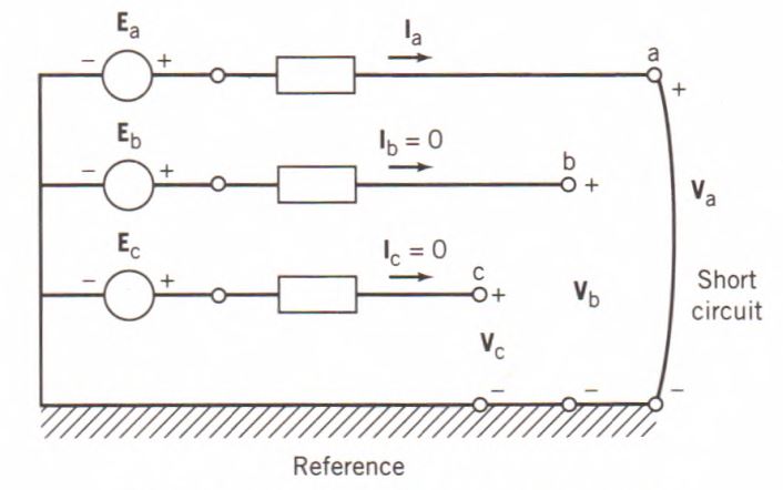
Figure1: A single line-to-ground fault.
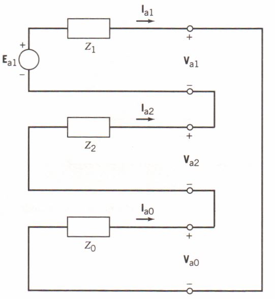
Figure 2: Interconnection of sequence networks of the single line to ground fault
Line-to-Line Fault
A line-to-line (L-L) fault involves a short circuit between two phase conductors that are assumed to be phases b and c. Therefore, there is symmetry with respect to the principal phase a. A line-to-line fault is illustrated in Fig. 3.
Assuming that pre-fault currents are negligible, the voltage and current relationships describing the line-to-line fault are given by
$\begin{matrix} {{V}_{b}}={{V}_{c}} & {} & \left( 9 \right) \\\end{matrix}$
$\begin{matrix} {{I}_{b}}=-{{I}_{c}}; & {{I}_{a}}=0 & \left( 10 \right) \\\end{matrix}$
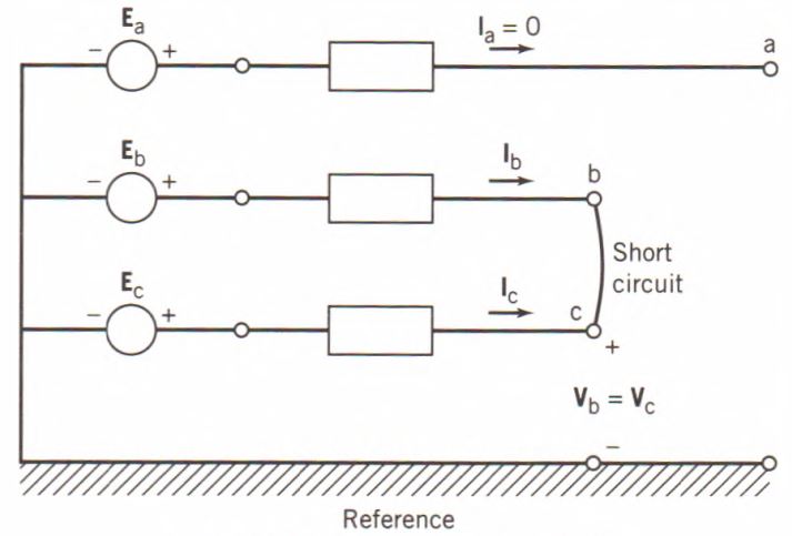
Figure 3: A line-to-line fault.
The sequence components of the short-circuit current are found by using the following Equation. Thus,
\[\begin{matrix} \left[ \begin{matrix} {{I}_{a0}} \\ {{I}_{a1}} \\ {{I}_{a2}} \\\end{matrix} \right]=\frac{1}{3}\left[ \begin{matrix} 1 & 1 & 1 \\ 1 & a & {{a}^{2}} \\ 1 & {{a}^{2}} & a \\\end{matrix} \right]\left[ \begin{matrix} {{I}_{a}} \\ {{I}_{b}} \\ {{I}_{c}} \\\end{matrix} \right]=\frac{1}{3}\left[ \begin{matrix} 0 \\ \left( a-{{a}^{2}} \right){{I}_{b}} \\ \left( {{a}^{2}}-a \right){{I}_{c}} \\\end{matrix} \right] & {} & \left( 11 \right) \\\end{matrix}\]
Therefore, it is seen that the negative-sequence component of the current is equal to the negative of its positive-sequence component; that is,
$\begin{matrix} {{I}_{a2}}=-{{I}_{a1}} & {} & \left( 12 \right) \\\end{matrix}$
The voltages of the shorted phases, b and c, may be expressed in terms of the sequence components as follows:
$\begin{matrix} {{V}_{b}}={{V}_{a0}}+{{a}^{2}}{{V}_{a1}}+a{{V}_{a2}}=0 & {} & \left( 13 \right) \\\end{matrix}$
$\begin{matrix} {{V}_{c}}={{V}_{a0}}+a{{V}_{a1}}+{{a}^{2}}{{V}_{a2}}=0 & {} & \left( 14 \right) \\\end{matrix}$
Subtracting Eq. 14 from 13 gives
$\begin{matrix} {{V}_{b}}-{{V}_{c}}=({{a}^{2}}-a){{V}_{a1}}+(a-{{a}^{2}}){{V}_{a2}} & {} & \left( 15 \right) \\\end{matrix}$
Because Vb and Vc are equal, Eq. 15 reduces to zero and yields
$\begin{matrix} {{V}_{a1}}={{V}_{a2}} & {} & \left( 16 \right) \\\end{matrix}$
Equations 12 and 16 indicate that the positive- and negative-sequence networks are to be interconnected in parallel for a line-to-line fault. This is illustrated in Fig. 4.
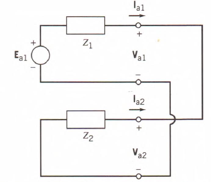
Figure 4: Interconnection of sequence networks for a line-to-line fault.
Double Line-to-Ground Fault
A double line-to-ground (2LG) fault involves a short circuit between two phase conductors b and c and ground. As with the line-to-line fault, there is symmetry with respect to the principal phase a. A double line-to-ground fault is illustrated in Fig. 5.
For a 2LG fault with pre-fault currents assumed negligible, the voltage and current relationships are given by the following:
$\begin{matrix} {{V}_{b}}={{V}_{c}}=0 & {} & \left( 17 \right) \\\end{matrix}$
$\begin{matrix} {{I}_{a}}=0 & {} & \left( 18 \right) \\\end{matrix}$
The sequence components of the voltage at the fault location are found by using following equation. Thus,
\[\begin{matrix} \left[ \begin{matrix} {{V}_{a0}} \\ {{V}_{a1}} \\ {{V}_{a2}} \\\end{matrix} \right]=\frac{1}{3}\left[ \begin{matrix} 1 & 1 & 1 \\ 1 & a & {{a}^{2}} \\ 1 & {{a}^{2}} & a \\\end{matrix} \right]\left[ \begin{matrix} {{V}_{a}} \\ 0 \\ 0 \\\end{matrix} \right]=\frac{1}{3}\left[ \begin{matrix} {{V}_{a}} \\ {{V}_{a}} \\ {{V}_{a}} \\\end{matrix} \right] & {} & \left( 19 \right) \\\end{matrix}\]
Therefore, it is seen that the sequence components of the voltage at the fault are all equal; that is,
$\begin{matrix} {{V}_{a1}}={{V}_{a2}}={{V}_{a0}} & {} & \left( 20 \right) \\\end{matrix}$
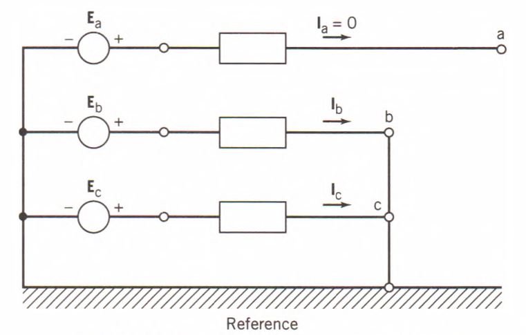
Figure 5: A double line-to-ground fault.
Neglecting pre-fault load currents, the current in phase a may be expressed as
$\begin{matrix} {{I}_{a}}={{I}_{a0}}={{I}_{a1}}={{I}_{a2}}=0 & {} & \left( 21 \right) \\\end{matrix}$
Equations 20 and 21 indicate that the three sequence networks are to be interconnected in parallel for a double line-to-ground fault. This is illustrated in Fig. 6.

Figure 6: the interconnection of sequence networks for a double line to ground fault
Three-Phase Fault
A three-phase fault, although it is a symmetrical fault, may also be analyzed using the method of symmetrical components. Consider the three-phase fault illustrated in Fig. 7. Assuming the pre-fault currents are negligible, the voltage and current relationships describing this fault are
\[\begin{matrix} {{V}_{a}}={{V}_{b}}={{V}_{c}} & {} & \left( 22 \right) \\\end{matrix}\]
$\begin{matrix} {{I}_{a}}={{I}_{b}}={{I}_{c}}=3{{I}_{a0}}=0 & {} & \left( 23 \right) \\\end{matrix}$
Equation 23 confirms that there is no zero-sequence current for a three- phase fault; that is, Ia0 is identically equal to zero. The positive- and negative- sequence components of the voltage at the fault location are found as follows:
$\begin{matrix} {{V}_{a1}}=\frac{1}{3}\left( {{V}_{a}}+a{{V}_{b}}+{{a}^{2}}{{V}_{c}} \right)=\frac{1}{3}\left( 1+a+{{a}^{2}} \right){{V}_{a}}=0 & {} & \left( 24 \right) \\\end{matrix}$
\[\begin{matrix} {{V}_{a2}}=\frac{1}{3}\left( {{V}_{a}}+{{a}^{2}}{{V}_{b}}+a{{V}_{c}} \right)=\frac{1}{3}\left( 1+{{a}^{2}}+a \right){{V}_{a}}=0 & {} & \left( 25 \right) \\\end{matrix}\]
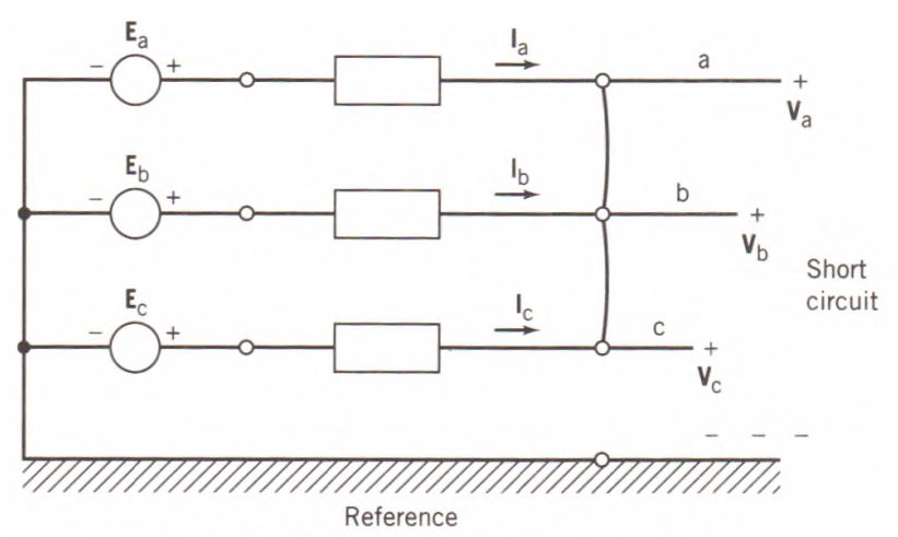
Figure 7: A three-phase fault
Since the positive- and negative-sequence components of the voltage at the location of the fault are both equal to zero:
$\begin{matrix} {{V}_{a1}}=-{{I}_{a1}}{{Z}_{1}}+{{E}_{a1}} & {} & \left( 26 \right) \\\end{matrix}$
$\begin{matrix} {{V}_{a2}}=-{{I}_{a2}}{{Z}_{2}} & {} & \left( 27 \right) \\\end{matrix}$
The sequence components of the current are obtained from Eqs. 26 and 27 as follows:
$\begin{matrix} \begin{align} & {{I}_{a1}}=\frac{{{E}_{a1}}}{{{Z}_{1}}} \\ & {{I}_{a2}}=0 \\\end{align} & {} & \left( 28 \right) \\\end{matrix}$
It has been found that no zero- and negative-sequence currents are flowing during a three-phase fault. Therefore, the analysis of a three-phase fault involves only the positive-sequence network, which is shown in Fig. 8.
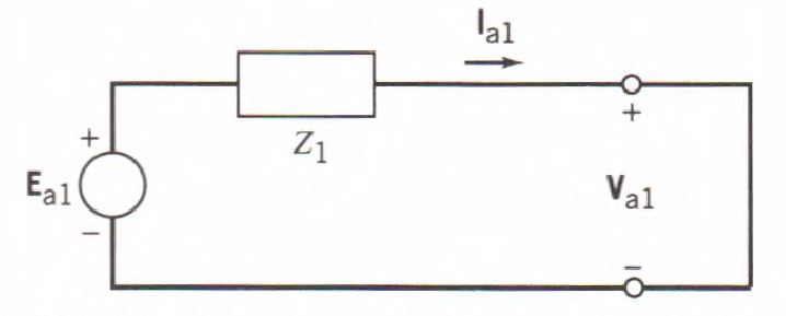
Figure 8: Sequence network for a three-phase fault.
Faults in Power System Key Takeaways
Understanding and analyzing faults in power systems—especially both symmetrical and unsymmetrical types—is critical for the safe, reliable, and efficient operation of electrical networks. Fault analysis enables engineers to calculate fault currents and voltages accurately, which directly informs the design of protection schemes such as circuit breakers, protective relays, and coordinated settings. These systems are essential to prevent extensive damage to power equipment, ensure quick fault isolation, and maintain overall system stability, particularly during transient disturbances. Moreover, accurate fault studies are integral to transient stability analysis, which helps assess whether a power system can continue operating synchronously after a fault or major disturbance.