This article covers the computer design and components, as well as technologies relating to data storage and file formats. By becoming familiar with the computer’s components and technologies, you will have laid a foundation on which to build further knowledge, either in your studies as a PC technician or in casual reading about new computer technologies.
The overall design of a computer can be divided into four major systems: input, output, processing, and storage. See Figure 1.
Nearly all computers used today still use the same basic four types of equipment designed in the mid-1940s. Computers contain equipment pieces but are designed and programmed to work as a single unit. The basic design of every computer includes:
- An input device for entering data into the system.
- An output device for retrieving data from the system.
- A central processing unit (CPU) for processing the data.
- A storage device for storing programs and data.
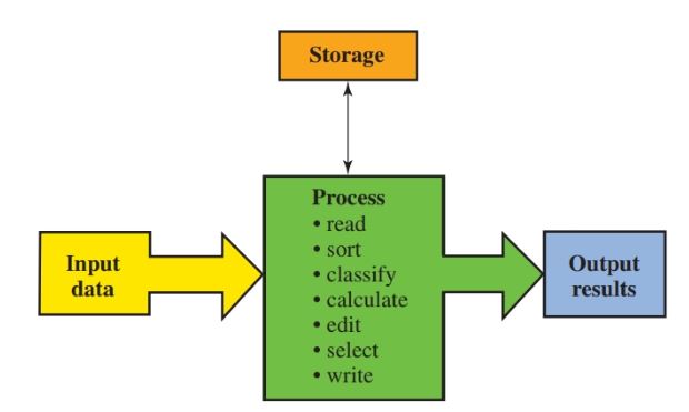
Figure 1. This diagram shows the flow of information through a computer.
Input can be any type of data, such as numbers, words, and symbols. Processing is done in a preset sequence as the computer follows a program’s instructions.
Programs and data are stored in memory. Output can be printed material, data sent to other equipment, or communication over the phone line. The remainder of this article will contain an overview of the various computer components and functions.
The Case
There are three classic case styles used for PCs: desktop, tower, and mini-tower, Figure 2.
The desktop, as its name suggests, generally sits on top of the user’s desk. The desktop’s wide surface makes an excellent platform for a monitor, and the case’s minimal height, about eight inches for a full-sized desktop, conveniently places the monitor at eye level with the user.
The tower, representative of its name, is a tall, narrow unit, designed to set on the floor, beside a desk, or inside of a cabinet; however, it can be placed on top of the desk if the user prefers.
The mini-tower is a modified version of a standard tower. It is slightly shorter than a typical tower model.
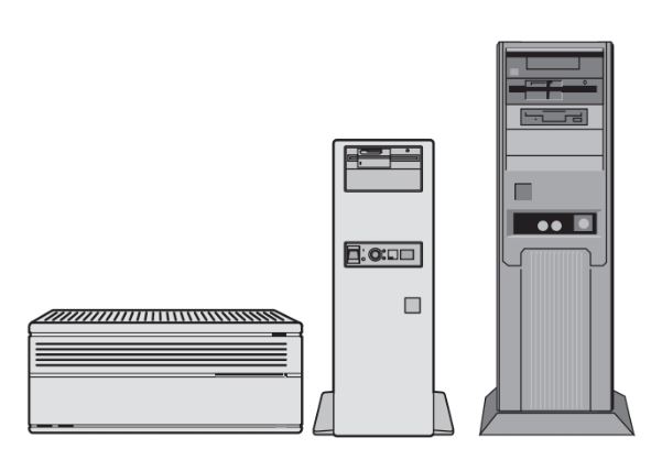
Figure 2. The three most common case styles are the desktop, mini-tower, and tower.
Case styles are left to the user’s taste, desk design, space limitations, or sometimes the requirements of the job.
However, one of the important aspects of selecting a case is the number of bays available for mounting devices such as a CD-ROM, floppy drive, DVD, and hard drive.
Some case styles have a limited number of bays, which could cause expansion or diversification issues with advanced use. See Figure 3.
External bays provide a location for installing devices such as floppy drives, DVD players, tape drives, and other accessories that are intended to be physically accessed by the user.
Internal bays provide locations inside the computer for devices such as hard drives, which do not need to be physically accessed by the user.
Unused external bays typically have a cover over each of the device bay areas. The cover can be easily removed, leaving the bay area exposed for installation of a device.
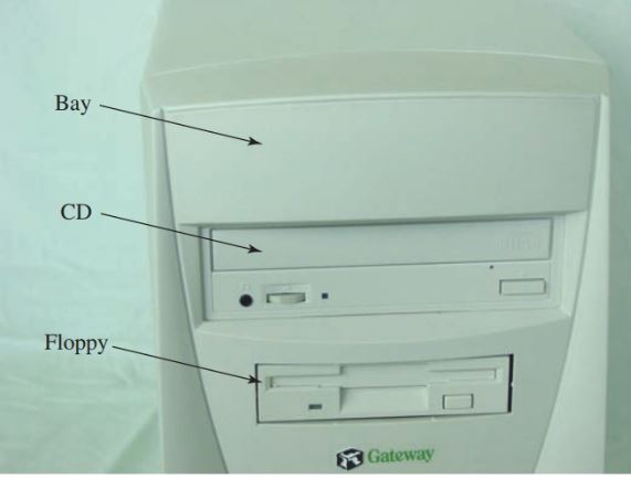
Figure 3. Computer bays and their use.
Form Factor
The case, motherboard, and power supply have what is known as a form factor. Some common form factors are XT, AT, Baby AT, ATX, and Mini ATX.
The form factor defines the physical attributes of the item, such as the length, width, and height.
In other words, the case, motherboard, and power supply form factors must match to be physically compatible with each other.
Input Devices
Input devices allow entry of data into the computer. The device is controlled by program instructions that send a command to an input or output (I/O) channel. Examples of these commands may be to enter a letterpressed on the keyboard or to move the cursor across the screen.
Input devices are also known as peripherals. Some examples of input devices include keyboards; an optical or wireless mouse; a roller ball or touch pad; and a game controller. Figure 4 lists examples of some common input devices.
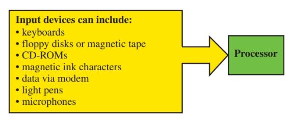
Figure 4. Listed are some examples of input devices.
Power Supply
The power supply converts standard 120-volt ac electrical energy into dc voltage levels. The typical dc voltage levels are +12, +5, +3.3, -12, -5 and zero or ground.
The power supply provides power to many devices used as part of the computer, such as the hard disk drive, floppy disk drive, and CD-ROM, Figure 5. It also supplies power to the motherboard.
The ATX power supply connection on the motherboard is a single unit that is “keyed.” This means that the connection on the motherboard is designed so that the power supply’s connector can fit into it only one way.
Earlier models, such as the AT and XT, used a pair of motherboard power connectors. Although these connectors were also “keyed,” technicians had to use care in connecting them to the motherboard because they could be easily switched, resulting in damage to the motherboard.
A memory aid in correctly connecting two power connectors to the motherboard is “black go back-to-back.” This means the black wire on each power connector should be next to the other when plugged into the motherboard.
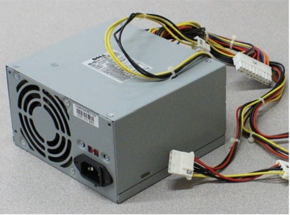
Figure 5. The power supply provides power to the motherboard and to other computer components.
Motherboard
The motherboard is a sophisticated electronic circuit board that provides the communication pathways between all major computer components.
The motherboard houses the CPU, memory, expansion slots, chipsets, BIOS, CMOS battery, an oscillator circuit, and other electronic components, Figure 6.
Small circuit paths called traces, running in parallel across the motherboard, Figure 7, provide a path for data, control signals, and power. The power supplied to the motherboard is limited to the low-wattage needs of the motherboard’s electronic components.
Components such as hard disk drives and CD drives, which require larger volumes of electrical energy, connect directly to the power supply.
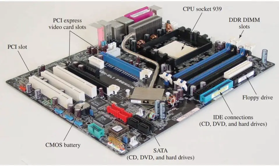
Figure 6. Major motherboard components.
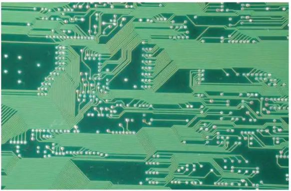
Figure 7. Circuit traces provide a path for data, control signals, and power.
The motherboard also provides slots for expansion cards. The slots provide a quick and easy way to connect to the motherboard bus system without the use of solder. An expansion card can be simply inserted into the slot.
The two main types of slots encountered are Industrial Standard Architecture (ISA) and Peripheral Component Interface (PCI). ISA is one of the oldest types of slots and was developed many years ago. It is not manufactured into boards any longer.
The PCI type of slot is standard today. A single Accelerated Graphics Port (AGP) may be encountered only for video card use. Video cards are designed to offer greater enhancements than standard video circuits built into a typical motherboard.
Video cards often contain their own BIOS, additional RAM, and a processing unit, such as an accelerator or a coprocessor, to support high- speed graphics and to operate with minimum CPU intervention. See Figure 8.
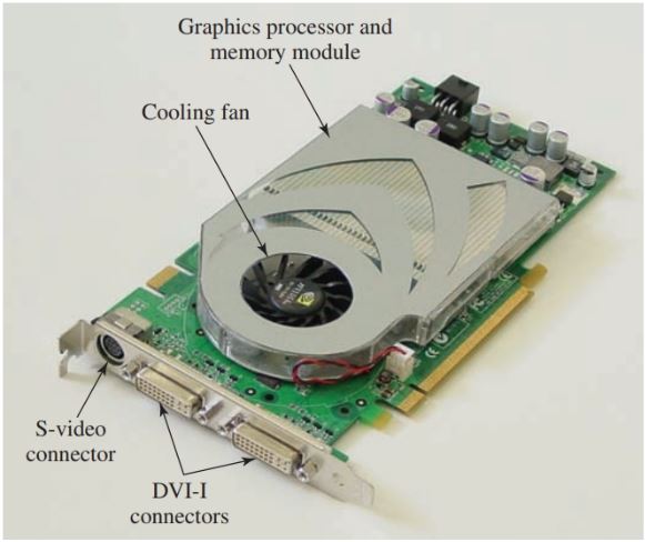
Figure 8. This video card has an S-video connector and DVI-I connectors. Its GPU provides support with little or no motherboard CPU intervention.
Computer motherboards have a variety of external port connections. The exterior ports of a motherboard are shown in Figure 9. Notice on this motherboard there are two RJ-45 ports used for networking, which is an enhanced feature.
The LAN-2 port is used to share the Internet connection with another computer. The audio input and output ports, the coaxial audio out port, and the Tosk link audio out port are designed to support entertainment.
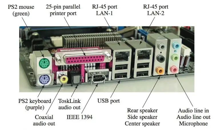
Figure 9. Motherboard port connections.
CPU
The central processing unit (CPU), or microprocessor, processes all software program instructions and is responsible for manipulating data. It also contains an arithmetic/logic unit, which handles all mathematical computations.
The CPU is the most expensive integrated circuit in the computer. A typical CPU contains millions of transistors and integrated circuits that are programmed to process information.
CPUs are generally compared by the working frequency, such as 3.4 GHz or 3 GHz. However, speed is only one factor in measuring CPU performance.
Other factors that greatly improve the performance of a CPU are the CPU’s instructional command set, on-chip cache, and the parallel processing of instructions.
The CPU instruction set is the actual set of commands the CPU understands. These commands are used to process data through the CPU.
On-chip cache is a small amount of memory used to store data that is frequently accessed by the CPU. Because the memory is integrated into the chip and does not need to transfer data across the motherboard, the processing speed of the CPU is increased.
Parallel processing is a technology that is designed to process more than one set of instructions or data through a CPU at the same instant.
By processing more than one piece of data, speed appears to be double the rated frequency of the unit. There are other factors that affect the overall performance of a computer such as a motherboard bus speed, the amount of RAM, the version of operating system, as well as the types of physical interfaces used to connect to other components.
Early processors consisted of a single CPU and cache packaged as a single chip. Intel and AMD have both introduced dual-core and quad-core processors.
A multi-core processor consists of separate processors that share a single bus and cache system. The dual-core processor has the same effect on a computer as if two separate processors or CPUs are installed on the same motherboard, and they share the responsibility of processing computer data.
Modern CPUs run at very high frequencies when compared to their early predecessors. The high frequencies produce a great deal of heat inside the CPU structure.
To prevent damage to the CPU caused by excessive heat, cooling technologies, such as fans and heat sinks, must be applied. See Figure 10.
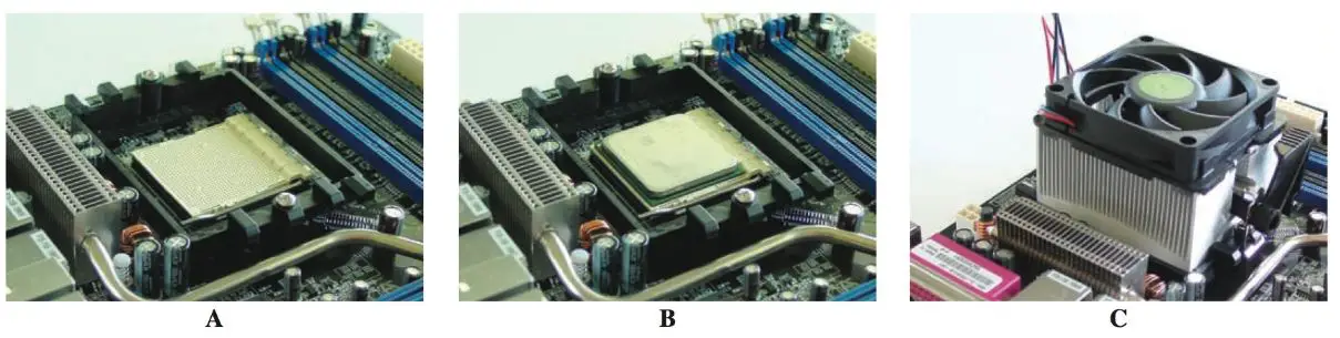
Figure 10. A—The socket used to house the dual-core processor. B—A thermo compound paste ensures a good bond between the CPU and the heatsink. C—The heatsink and cooling fan are installed over the CPU.
Memory
There are two main types of memory used in a computer, RAM, and ROM. Both are classified by their ability to retain program data and instructions after power is no longer supplied to the chip.
The contents of read-only memory (ROM) are retained after the power to the computer is turned off. The ROM chip located on the motherboard is called the BIOS.
The BIOS contains programming that is vital to the computer’s operation. It would be impossible for the computer to run without a BIOS.
Random access memory (RAM) is a temporary storage area that loses content when electrical power is interrupted. The contents of RAM constantly change as you load and unload different programs.
When you are finished with one program and start another, the new program is loaded into RAM, replacing the last program. It is also possible to load more than one program into RAM and then switch between the programs. This is called multitasking.
There are two main types of RAM used in computers, dynamic and static.
Dynamic RAM (DRAM) is composed of millions of transistors and capacitors, Figure 11. The capacitors are used to maintain a charge at the base of the transistor. The charge of the capacitor determines if the transistor is open or closed across the emitter and collector.
The open or closed condition represents data stored as a binary one or zero. The capacitors hold electrical charges in patterns matching the binary data patterns. While large capacitors can hold an electrical charge for a long period of time, the microscopic-sized IC capacitors cannot.
Because the capacitors lose their charge quite rapidly, they must be constantly recharged. The constant recharging is referred to as refreshing, and how often it occurs is called the refresh rate. Typically, DRAM needs to be refreshed thousands of times per second.
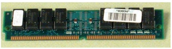
Figure 11. Basic DRAM found in older PCs.
Static RAM (SRAM) is composed mainly of digital flip-flops that retain their state of one or zero until the power is removed from the chip, Figure 12. SRAM is much faster and more expensive than DRAM.
SRAM is typically used when small amounts of memory are incorporated into other devices to enhance their performance.
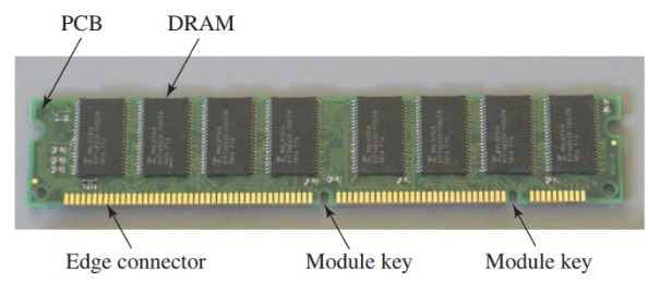
Figure 12. SDRAM found in many PCs.
For example, the CPU has a small amount of RAM incorporated into the chip. This small amount of RAM is called cache (pronounced cash) and is composed of SRAM.
Synchronous DRAM (SDRAM) is an enhanced version of DRAM found in many computers. The S represents synchronous, not static. The SDRAM runs in synchronization with the CPU, producing a higher overall memory performance than simple DRAM.
Because the SDRAM data transfer is coordinated to match the CPU timing, there is no delay before transferring data to and from the main memory as with earlier versions of memory technologies.
Another form of the special DRAM is double data rate- DRAM (DDR-DRAM). DDR-DRAM is designed to transfer data at twice the normal data rate transfer speed. Until DDR-DRAM, data was transferred at the same rate as one complete digital signal cycle. DDR technology transfers data on both the rising and falling edge of a digital pulse. See Figure 13.

Figure 13. DDR-DRAM can achieve data rate transfers twice as high as conventional DRAM by transferring data on both the rising and falling edge of the digital pulse.
DDR2 is the next generation of DDR memory. DDR2 operates at a lower voltage than DDR. The lower voltage counters the heat effect of the higher bandwidth produced by the module.
DDR2 uses a different motherboard socket from DDR and is not compatible with motherboards designed for DDR. The DDR2 DIMM key will not align with the DDR DIMM key. If the DDR2 is forced into the DDR socket, it will damage the socket, and the memory will be exposed to a high voltage level.
SIMM, DIMM, and SODIMM are PC memory chips that are packaged in several different styles.
SIMM
A single inline memory module (SIMM) is a row of DIP memory chips mounted on a circuit board that is inserted into a memory slot sockets on the motherboard. The SIMM is designed so that, when plugged into the memory socket, each side of the edge connector is the same circuit.
DIMM
A dual inline memory module (DIMM) is constructed similarly to a SIMM, Figure 14. The major difference is that the edge connectors directly across the circuit board from each other do not connect electrically. They are not the same electrical connection as they are on a SIMM. The DIMM design allows for more electrical connections per inch than the SIMM design.

Figure 14. Various memory packages can be easily identified by size. Shown are two SIMMs, the DIMM, the DDR, and the DDR2.
SODIMM
Small Outline DIMM (SODIMM) is a very compact form of DIMM memory. It is specifically designed for compact portable devices, such as laptop or notebook computers. SODIMM is available as DDR2, as well as DDR.
BIOS
The computer basic input output system (BIOS) contains the programming necessary to start the computer and then hand control over to the operating system. The BIOS program performs several crucial functions. See Figure 15.
First, it starts the computer when power is applied to the PC. The BIOS performs a power-on self- test (POST). The POST checks to see if major components, such as memory chips, CPU, power supply, video circuitry, keyboard, and hard disk drive, are in working order.
It does not perform detailed checks, but rather a basic set of tests to identify that the components are installed, have power, and appear to be in working order.
Later, when the POST is complete and the actual operating system is installed, a more detailed check is performed. The BIOS also automatically detects any new hardware that has been added to the system since the last time the computer was started.
Detecting and installing the communications necessary for a new piece of hardware is referred to as plug and play (PnP) technology.
Plug and play mean that most hardware devices designed today can be automatically detected at startup, install all necessary software programs, and begin working immediately. For example, if you install a new sound card, the system should automatically detect it and install the necessary software to finish setting up the card.
It should be noted that plug and play does not automatically detect and configure all hardware. Therefore, hardware still often requires human intervention for setup.
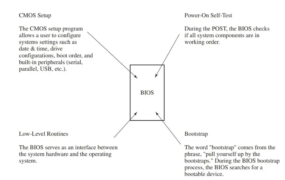
Figure 15. Basic functions of the BIOS.
The BIOS also contains the CMOS (pronounced seemoss) setup program. This program, normally accessed during bootup, allows a user to configure system settings such as date and time, drive configurations, boot order, and built-in peripherals (serial, parallel, USB, etc.).
The settings are not saved in the BIOS but are stored in CMOS. CMOS, which stands for a complementary metal oxide semiconductor, is a type of memory that can hold its data even after the computer is turned off, as long as it receives power from a lithium battery.
In the earlier computer systems, CMOS was located in the real-time clock (RTC) chip. Today CMOS is located in the chipset.
The original BIOS chip was a true ROM, meaning that a program could only be written once to the chip. The ROM could not be erased and rewritten to.
Today’s more modern BIOS is actually referred to as flash memory because a new program can be flashed into, or written in, the BIOS chip.
Chipsets
A chipset is an integrated circuit on the motherboard containing control circuitry that interfaces to the computer’s subsystems, such as memory, CPU, and input and output devices, Figure 16.
Chipsets are designed to carry out instructions that do not require CPU intervention. The earliest computers processed all instructions and all data directly through the CPU.
As the computer evolved, it became apparent that many redundant processes did not require the continuous intervention of the CPU. For example, when a program loads or transfers data from a floppy disk or the hard drive, it needs to go directly to RAM, where it will be executed.
Since each bit of data or program does not need to be processed by the CPU, direct memory access (DMA) was developed so that the data could go directly to the RAM from the storage media, such as a floppy disk or the hard drive.
Today, chipsets inserted into key points along the motherboard bus support the direct movement of data from the floppy or hard disk drive to the RAM. See Figure 17.
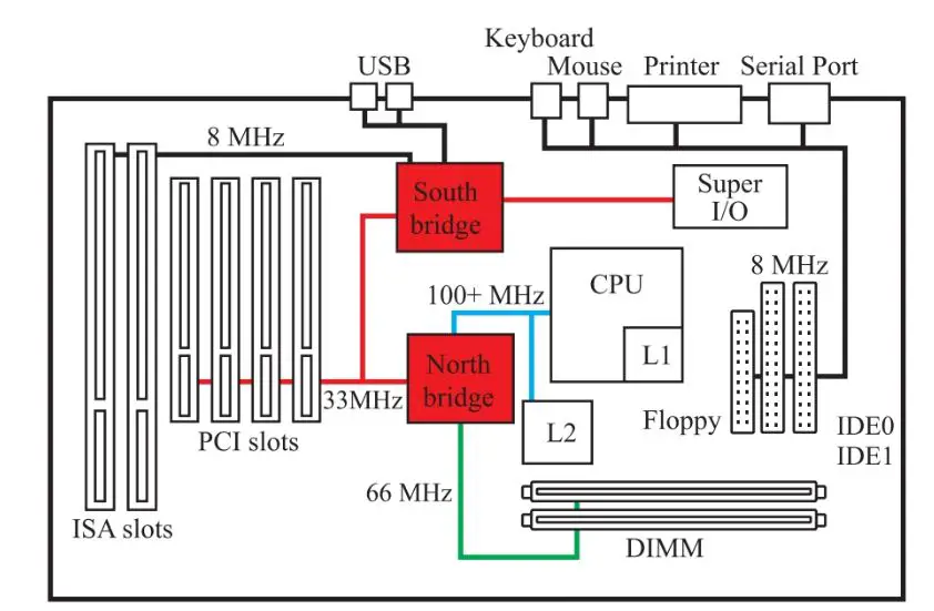
Figure 16. The chipset is commonly divided into the northbridge and the south bridge. The northbridge is used to transfer and control higher data speed systems, such as graphics and DVD hardware. The south bridge controls the slower devices associated with the PCI and ISA buses.
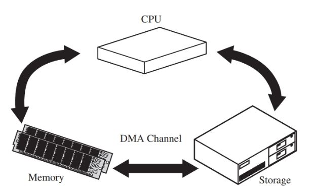
Figure 17. In older computers, all data and instruction had to flow through the CPU. With direct memory access (DMA), the CPU allows data to flow directly to RAM from many different computer devices. This allows the CPU to concentrate on other duties, producing a more efficient system.
A similar technology, known as bus mastering, was developed to move data between any two major components in a computer, such as a modem to the hard drive, a floppy drive to a modem, or a network card to the hard drive.
Typically, bus mastering moves data from a port to a device, such as a serial port to a hard drive. Bus mastering also relies on a special set of chips built into the motherboard that permit data to move between two devices without going directly through the CPU.
Mass Storage Devices
Two main technologies used to store massive amounts of data are magnetic storage devices and optical, or laser, devices. The hard disk drive, floppy drive, ZIP drive, and tape drive use magnetic principles for storing data. CD-ROM, CD-RW, and DVD use laser light technology to store and retrieve data.
Two of the most common magnetic storage devices associated with computers are floppy disk drives and hard disk drives.
Each utilizes data storage based on magnetic principles with which you are already familiar. As you know from earlier studies, electricity can produce magnetism, and magnetism can produce electricity. Using these principles, magnetic patterns representing digital patterns of ones and zeros can be stored and retrieved from special disks, Figure 18. The disks are coated with an iron oxide material that is easily magnetized.
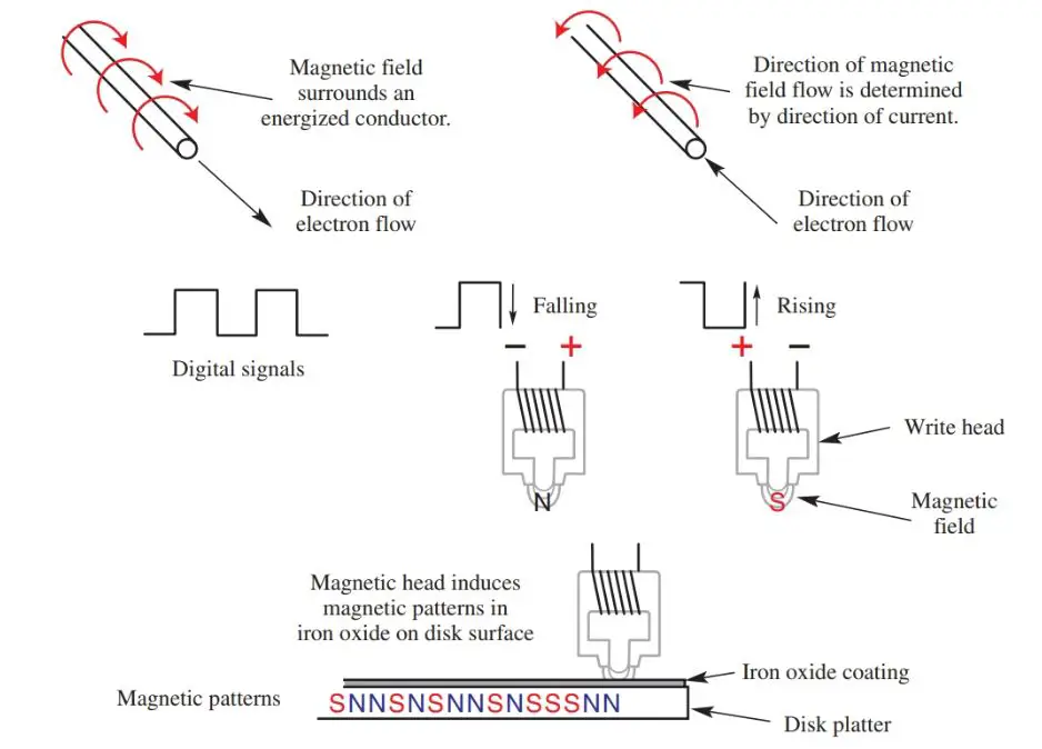
Figure 18. At the top, the current flowing through a conductor produces a magnetic field. This field is concentrated in a magnetic write head (middle). The write head is then used to create patterns on a disk or tape surface (bottom).
A hard disk drive is very simple in construction. It contains one or more platters that are coated with a special iron oxide.
The iron oxide retains magnetism induced by the read/write head attached to the end of the actuator arm. The magnetic patterns are in response to digital pulses sent to the read/write head from the computer motherboard and CPU.
The digital pulses represent computer data. Converting the digital pulses into magnetic patterns on the disk surface is called writing data to the disk. The operation can be reversed to retrieve data from the disk.
The fast-moving magnetic patterns on the disk cause magnetic lines of force to cut across the read/write head, producing digital pulses representing the stored data on the disk. The process of retrieving data from the disk platter is called reading.
The file allocation table (FAT) is used by the operating system to keep track of files on a disk. The FAT includes information such as the name, date, and time of the creation or modification of a file; the file’s location; and the number of sectors used by the file.
The file allocation table also records the location of every area on the disk that is used for storage. Storage areas are referred to as sectors.
The FAT is the oldest and longest used file system for personal computers. The original FAT16 file system was developed for the early disk operating system (DOS).
Although DOS has been virtually replaced by recent Windows operating systems, the FAT16 system can still be used by these systems.
The two common FAT systems are FAT16 and FAT32.
FAT16 is so named because it uses a maximum of 16 bits to identify each sector on a disk. FAT32 uses a maximum of 32 bits for sector identification.
The new technology file system (NTFS) was developed for the Windows NT operating system. The file system is structured similarly to FAT16 and FAT32, but it is greatly enhanced to provide better security and large disk access.
CD Drives
CD-ROM (read-only), CD-R (recordable), CD-RW (read/write), and DVD technology are all very similar. All of these technologies use laser diodes to read the discs. See Figure 19.
CD-R and CD-RW drives can also write to a disc and store data on the disc as a series of lands and pits. A land is in reference to the disc’s surface, and pits are actual pits in the CD-ROM disc. The lands and pits symbolize the ones and zeros that represent the data.
CD-R and CD-RW technologies are similar except that the land and pit areas are simulated through the use of a photosensitive material inside the disc.
The photosensitive material can be made to resemble the land and pit areas used in the traditional disc system by applying higher-than-normal laser light to the organic material.
When the higher-than-normal laser light strikes the organic material, the organic material will no longer reflect light. By no longer reflecting light, it represents data, the same way the pit areas do on the DVD.
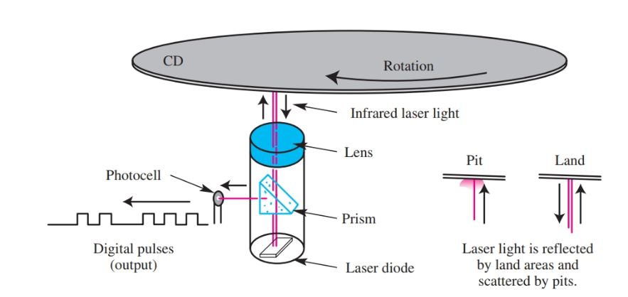
Figure 19. A laser diode sends a beam of light through a prism and onto the CD. If the light hits a land, the light is reflected back. Pits disperse the light. The reflected light travels back through the prism, which sends some of the light to a photocell. The photocell turns the light into digital electrical pulses.
The DVD players use laser optic technology to play back the data stored on the disc. Rather than using the conventional infrared laser diode as a source of light, the DVD system uses a new laser diode that produces light in the blue spectrum. This means the light has a shorter wavelength. This makes the system capable of reading a smaller pattern of pits on the disc, Figure 20. This allows more data to be stored on a disc.
The double-sided, dual-layer disc can store up to 17 gigabytes of data, or 8.5 gigabytes on each side of the disc. See Figure 21.
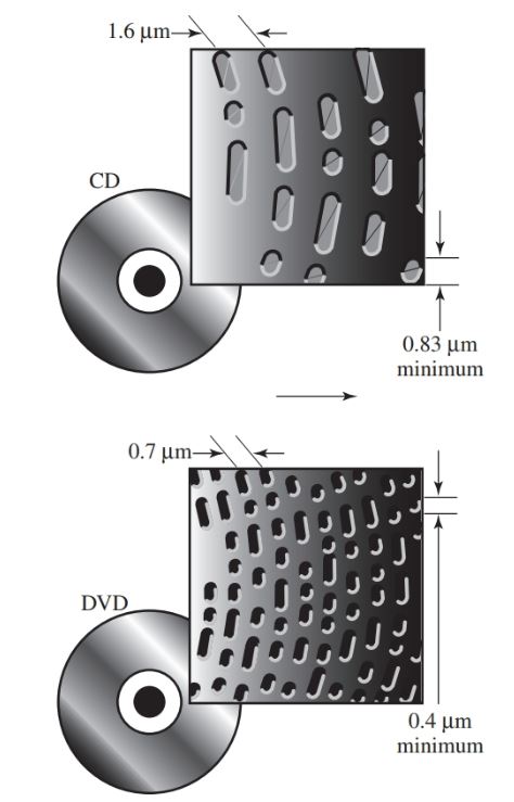
Figure 20. DVD players emit a blue light with a shorter wavelength than conventional CD players. This allows smaller and more densely packed pits to be imprinted on the discs.
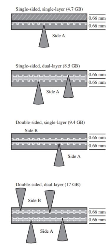
Figure 21. Four different disc layouts. Single-sided, single-layer discs can hold approximately 4.7 gigabytes of information. Double-sided, double-layer discs can hold about 17 gigabytes of information.
The digital video disc is a high-capacity storage medium, which is used to store full-length movies, computer programs, and other information.
While the typical compact disc can store 650 megabytes of information, the DVD can store up to 17 gigabytes. This is over 25 times the storage capacity on the same size disc.
In addition to the storage capacity, DVD uses the MPEG format for compressing the video data. The combination of the greater storage capacity and the MPEG compression allows for several hours of video play.
The demand generated by high-definition television and movie industries for better video recording media has led to HD-DVD and Blu-ray Disc formats. Blu-ray Disc is a new high-definition video and data format developed jointly by consumer electronics and PC groups called the Blu-ray Disc Association.
Both HD-DVD and Blu-ray Disc are also used as a data storage media for computers. Sony released the first laptop computer with a Blu-ray Disc device in 2006. The HD-DVD approach is to preserve as much previous DVD design technology to ensure downward compatibility while increasing storage capacity.
The Blu-ray Disc approach focuses more on achieving the greatest possible storage capacity while not necessarily ensuring downward compatibility with previous CD and DVD designs.
The standard DVD capacity is far less than what is required to record movies and television programs in high-definition format. As a result, HD-DVD was developed for recording capacity of 15 GB for single-layer media.
The capacity of a single-layer Blu-ray Disc is 25 GB. The storage capacity doubles for dual-layer disc format. Future storage capacities are expected to exceed 100 GB as the technology is refined.
Note that the term disc is spelled differently. When talking about CD and DVD technology, the correct spelling is “disc”. When talking about magnetic storage, the correct spelling is “disk.”
A typical CD-ROM encodes data in a spiraling path from the center of the disc to its outer edge, Figure 22. Like magnetic storage devices, CD devices also use a special file format similar in design to the original FAT. Figure 22
The CD-ROM file system (CDFS) was originally introduced with Windows 95. Some other CD file formats are High Sierra Format, ISO9660, and Universal Disk Format (UDF).
The Optical Storage Technology Association (OSTA), formed by a group of manufacturers, created a file system structure called UDF that could be used for CD-RW, magneto-optical (MO) disc, and DVD technologies. UDF is the successor to the ISO9660 file structure. One of the greatest improvements in UDF is that it allows for a bootable disc.
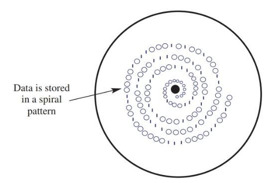
Figure 22. CDs store data differently than hard drives. CDs do not use sectors.
There are many compatibility issues today due to the many different CD file formats that are not downward compatible. For example, many CD-RW files cannot be accessed or read from older CD-ROM drive systems because of the way the file structure is organized and the intensity of the laser used.
Additionally, there are file systems designed especially for music and video, which only add to the compatibility problems between different CD drives.
Modem
The modem is used to support communications across telephone lines. Telephone lines were originally designed to transmit analog signals for voice, not digital, communication.
Since high-frequency digital signals will not pass through a typical telephone line leaving a home, digital data and commands must first be converted by the modem from digital format to analog.
In fact, the term modem is a contraction of two electronic terms that describe the general function of the modem—modulate and demodulate. A modulated signal is generated and encoded with data. The modulated signal is an analog signal, not digital.
When the modulated signal reaches its final destination, such as a modem on a distant computer, the modulated signal is then demodulated. That is, the encoded data in the analog signal is extracted and then converted back into digital codes. See Figure 23.
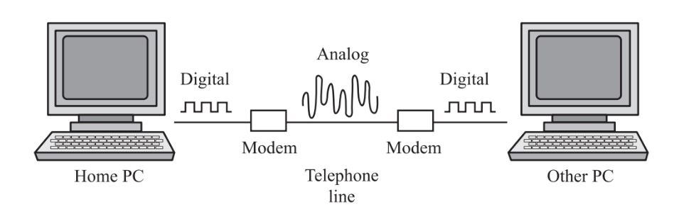
Figure 23. These two computers are connected by a modem. The signal coming from the first computer is digital until it passes through its modem. The modem converts the digital signal to an analog signal and passes it through the phone lines. The second computer’s modem receives the analog signal and converts it back to a digital signal that the computer can read.
Long spans of telephone networks are, in fact, digital. To be completely accurate, the digital signal in the PC is first converted to an analog signal. The analog signal is then converted back to a digital signal before it encounters telephone-switching gear located at the telephone company hardware.
The digital signal is transmitted across vast distances and then converted back to an analog signal when it is near its destination. At the destination computer, the modem converts the analog encoded signal to a digital signal.
The major chip responsible for how the modem works is called a universal asynchronous receiver/transmitter (UART), Figure 24. The UART converts the parallel digital data into a series stream of digital data and then encodes the digital signal into a modulated or analog signal.
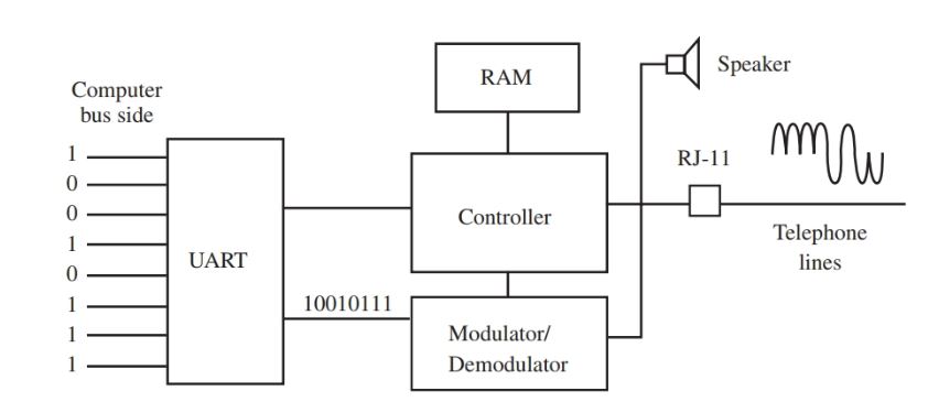
Figure 24. There are only a few major components in a modern modem. The UART is the most important.
Computer Design & Components Key Takeaways
Understanding computer design, components, and data storage technologies is essential for various practical applications in today’s digital world. The foundational knowledge of input, output, processing, and storage systems enables efficient troubleshooting, system upgrades, and optimization for both personal and professional computing needs. Familiarity with motherboard architectures, CPUs, memory types (RAM, ROM, DRAM, SRAM), and storage devices (HDDs, SSDs, optical drives) allows users to make informed decisions when building, repairing, or upgrading systems. Additionally, awareness of file systems (FAT, NTFS, CDFS) and data transfer technologies (DMA, bus mastering) ensures proper data management and system performance. As technology evolves—from traditional hard drives to high-capacity Blu-ray discs and advanced DDR memory—this knowledge becomes crucial for adapting to new innovations.