This article explores various input transducers used in electronic systems, focusing on their roles in audio and recording applications. It discusses devices like microphones, magnetic tape heads, and CD pickup systems, explaining how they convert physical energy into electrical signals.
A transducer is a device that changes the energy of one form into the energy of an entirely different form. When energy conversion occurs, work is performed. In audio systems, an input transducer is used to change sound energy into electrical energy. The output of an amplifying system is always applied to a transducer. The load device of a system is an output transducer. Functionally, the load may be resistive, inductive, and, in some cases, capacitive. Most of our applications have used resistive loads. Resistors generally change electrical energy into heat energy.
Microphones as Input Transducers
The input transducer of an amplifying system is primarily responsible for the development of the signal that is processed by the system. In audio systems, an input transducer is used to change sound energy into electrical energy. Systems that respond to frequencies above the human range of hearing are called radio frequency (RF) systems. Electromagnetic waves must be changed into electrical energy in this type of system. Radio and television receivers respond to RF signals. The type of input transducer used depends on the signal to be processed. RF systems pick up signals that travel through the air or through an interconnecting cable network. Audio frequency (AF) systems develop a signal where a system is being operated. Microphones, compact discs (CDs), and DVDs serve as input transducers.
The primary function of a microphone is to change variations in air pressure into electrical energy. These variations in air pressure are called sound waves and are a form of energy. The pressure changes of a sound wave are easily converted into voltage, current, or resistance. Microphones generally change sound energy into a changing voltage signal. Crystal microphones and dynamic microphones are widely used.
A crystal microphone generates voltage through a mechanical stress placed on a piece of crystal material. This action is called the piezoelectric effect. Rochelle salt crystals produce this effect. Synthetic ceramic materials respond in the same way. Both materials respond to changes in pressure by producing a voltage. Sound waves striking the crystal cause it to bend or squeeze together. Metal plates attached to opposite sides of the crystal develop a potential difference in charge (voltage). The output voltage is then routed away from the crystal by connecting wires.
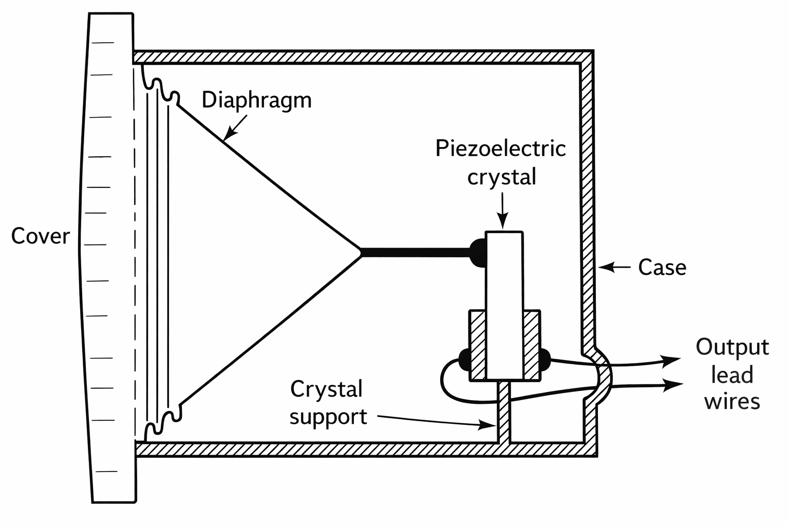
Figure 1. Crystal microphone.
Figure 1 shows the construction of a simplified crystal microphone internal structure. A dynamic microphone is considered to be a mechanical generator of electrical energy. The mechanical energy of a sound wave causes a small wire coil to move through a magnetic field. This action causes electrons to be set into motion in the coil. A difference in potential charge or voltage is induced in the coil. The resulting output of a dynamic microphone is AC voltage.
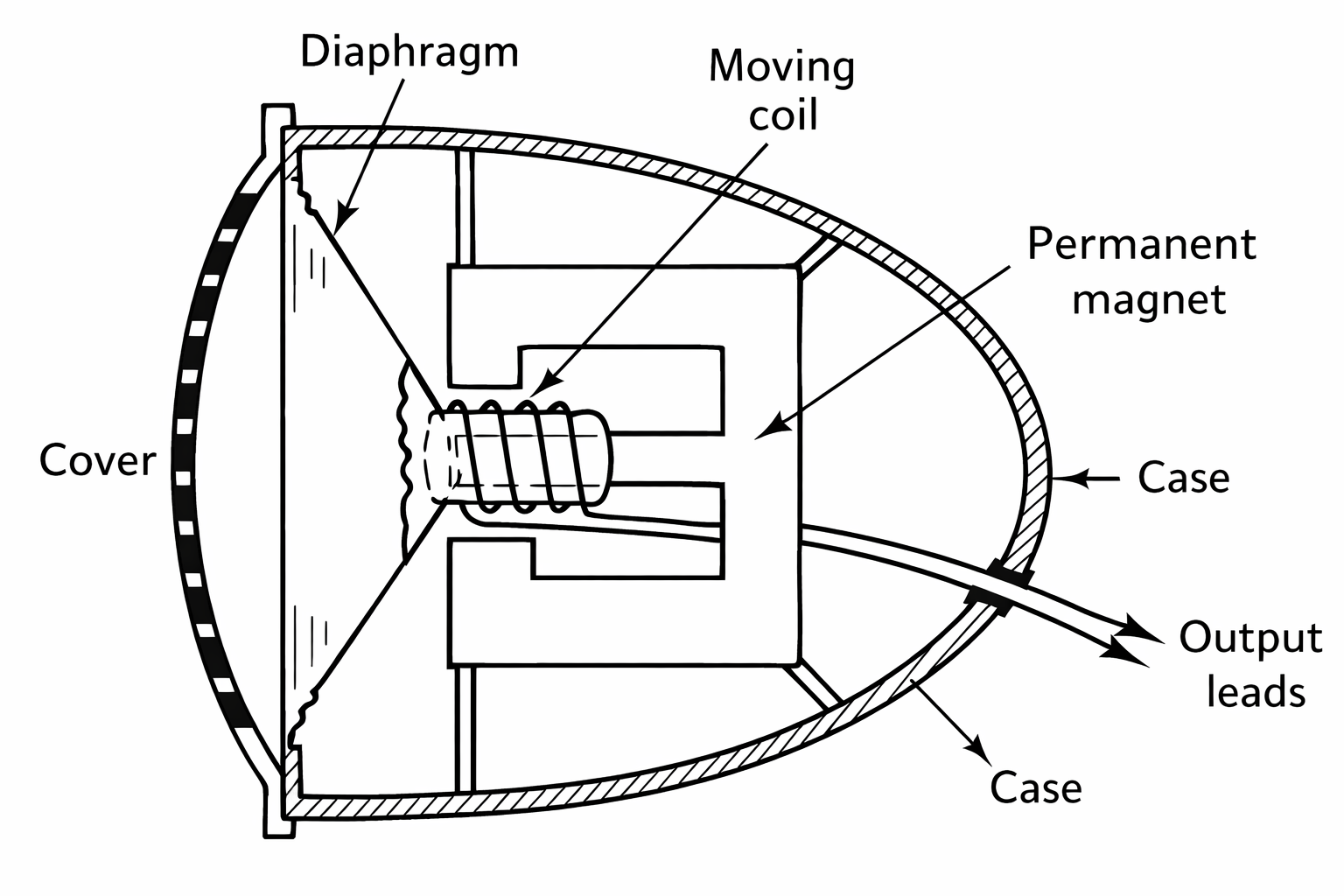
Figure 2. Structure of a dynamic microphone.
A simplified dynamic microphone is shown in Figure 2. Note that a lightweight coil of wire is attached to a cone-shaped piece of material. The cone piece is made of flexible plastic or thin metal. The cone is generally called a diaphragm. The diaphragm is attached to the outside frame of the microphone. Its center is free to move in and out when sound waves are applied. Sound waves striking the diaphragm cause it and the coil to move through a permanent magnetic field. Through this action, sound energy is changed into voltage. Flexible wires attached to the moving coil transport the signal voltage out of the microphone. This voltage is applied to the input of a sound system.
Magnetic Tape as an Input Device
Magnetic tape was, for many years, a common input for amplifying systems. As an example of converting electronic input variations to sound, let us look at how this was accomplished. Cassette tapes, which preceded compact discs (CDs) for recorded music, used this principle. A long strip of plastic tape is coated with iron oxide so that individual molecules of this material can be easily magnetized. A magnetic tape can, therefore, be used to store information in the form of minute charged areas.
Figure 3 shows how a sound signal can be placed on a magnetic tape. This is considered to be the recording function. Essentially, a sound signal is being applied to the electromagnetic head. Variations in the applied signal will cause a corresponding change in the electromagnetic field. Tape passing under the air gap of the head (such as a cassette tape) will cause oxide molecules to arrange themselves in a specific order. In a sense, a changing magnetic field is being transferred to the tape. The recorded signal will remain stored on the tape for a long period of time. Amplifying systems are used to place information on a tape. This process is achieved by speaking into a microphone. The signal is then processed by the amplifier. The output of the system supplies a signal current to the electromagnetic recording head. A motor-drive mechanism is needed to move the tape at a selected recording speed. The tape head responds as a load device when the system is recording sound information for reproduction.
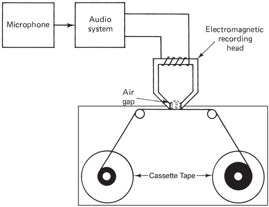
Figure 3. Tape recording function.
The recovery of information is achieved by the read head. This part of the system is like a dynamic microphone, except the electromagnetic coil is stationary. Voltage is induced in the coil by a moving magnetic field. As the magnetic tape moves under the read head, voltage is induced into the coil. Changes in the field cause variations in voltage values.
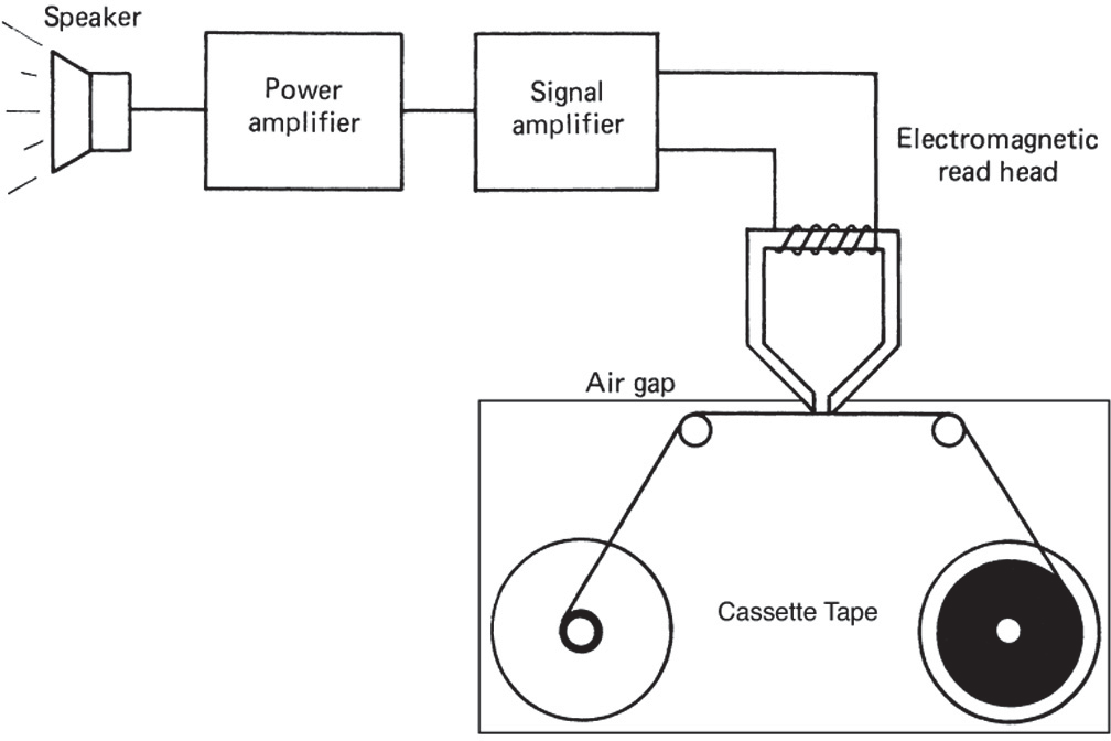
Figure 4. Tape reading or playback function.
Figure 4 shows a simplification of the tape-reading function. The tape head responds as an input transducer when the system responds as a playback device.
Compact Disc (CD) Players
The example of the magnetic tape device in the previous section showed how electromagnetic signal variations could be amplified and reproduced as sound. Compact disc (CD) players use an advanced form of this process.
In a CD player, sound is recorded on the surface of a CD to form “pits” and “flats.” A laser beam is focused onto the CD surface. As the CD rotates, the laser light varies according to “pits” and “flats” on the CD surface. The signal variations caused by the “pits” and “flats” of a CD track are amplified and reproduced as sound.
Review Questions
- A __________ is used to convert sound energy into electrical energy.
- A crystal microphone works on the __________ effect.
- A dynamic microphone converts sound waves into voltage using a __________ and a magnetic field.
- Magnetic tape is coated with __________ so that molecules can be magnetized.
- In a CD player, “pits” and “flats” are read by a __________ beam.
Answers
- microphone
- piezoelectric
- wire coil
- iron oxide
- laser
Key Takeaways
Input transducers such as microphones, magnetic tape heads, and CD pickup systems enable the transformation of physical stimuli like sound or magnetic fields into electrical signals. These signals can then be amplified, processed, or stored, which is fundamental to the operation of audio systems and media devices.