The article discusses the performance characteristics of a three-phase induction motor, including efficiency, power factor, current, and slip, using its equivalent circuit. It also presents torque calculations and how motor performance varies with changes in voltage and frequency.
Using the equivalent circuit of the three-phase induction motor and some additional information about the mechanical and core loses, one could calculate the performance of the three-phase induction motor from no-load to full-load. Figure 1 shows a set of generic curves of efficiency, current, power factor, and slip for an induction motor. Consider each of these curves.
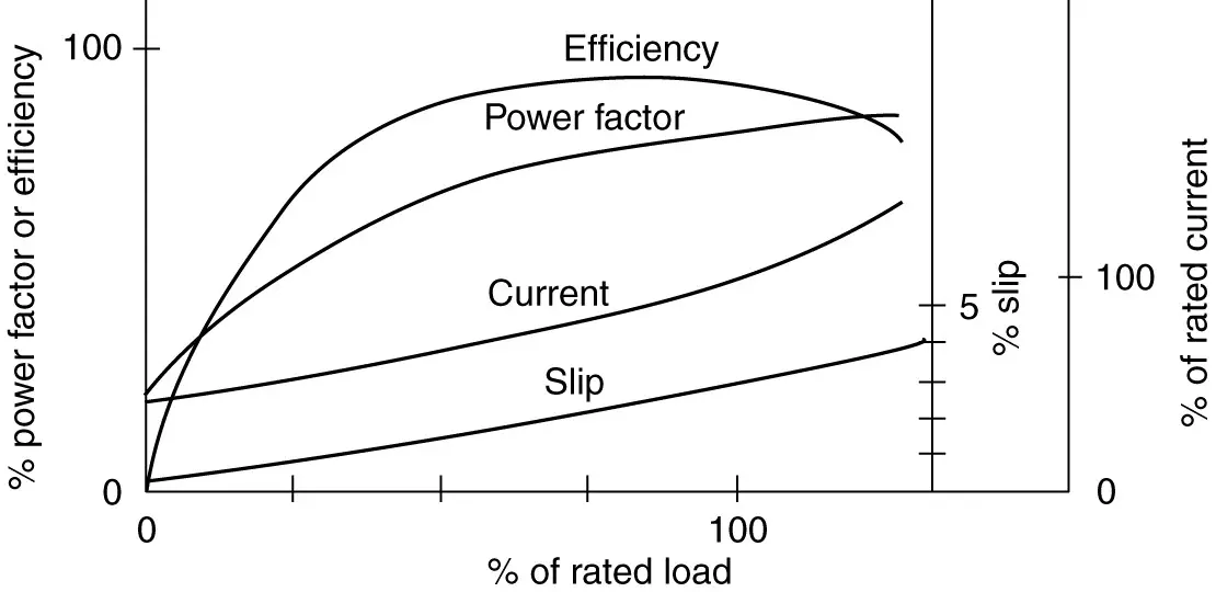
Figure 1 Characteristic curves of an induction motor.
Efficiency
Efficiency is the power out divided by the power in. Obviously, if there is no load on the motor, the power out and the efficiency are zero.
At no-load, the machine draws power from the system because there are still losses in the machine (rotational, core, and some copper). When a load is placed on the shaft of the motor, more power is drawn from the system and the efficiency must go up because the power out is now greater than zero. The efficiency will continue to increase as long as the output power increases faster than the input power.
Eventually, however, a point is reached at which the losses begin to grow faster and the efficiency rolls off. It is important to note that the efficiency is fairly flat from around 50% to 100% of rated load and peaks somewhere around 70% to 80%, so specifying a slightly oversized motor does not cause too much of a penalty in efficiency.
Power factor
Power factor is the real power into the machine divided by the apparent power. Considering the equivalent circuit shown in Figure 2, we note that for light loads the term Rr/s becomes very large due to the low value of slip. In particular, the rotor circuit is effectively an open circuit at no-load, and the equivalent circuit reduces to the stator resistance in series with the stator leakage reactance and the magnetizing reactance. The magnetizing reactance is much larger than the stator resistance, so the power factor is very low. It is not zero, however, because power is going into the motor to make up the no-load losses.
As the load increases, the real power into the machine must increase, while the reactive power doesn’t change too much. Reactive power maintains the magnetic field and is fairly independent of the load. Hence, we expect the power factor to increase as the load is increased on the motor. Operating a motor at less than rated load results in a lower power factor, which could aggravate power factor problems in a plant.
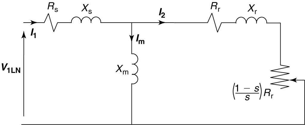
Figure 2 Per-phase induction motor equivalent circuit.
Current
Current is required to provide the reactive power for the magnetic field as well as for the real power to run the load. The no-load current can be a significant fraction of the full-load current because the air-gap of the motor is relatively large. As the load increases, the component of current in phase with the voltage increases, causing the magnitude of the current to increase while the power factor angle decreases.
Figure 3 shows a phasor diagram with the phase voltage as the reference phasor. The current, Inl, represents the line-current at no-load. Because no real-power is being delivered, the power factor is very poor. The current can be split into two components, one in phase with the voltage and the one lagging the voltage by 90o.
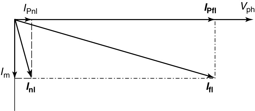
Figure 3 Current and voltage phasors for an induction motor.
The component in phase with the voltage produces real power, which in this case is just the losses of the motor. The component that lags by 90° is the magnetizing current, which creates the magnetic field and thus is associated with reactive power.
When the motor runs at full load, the magnetizing current remains approximately the same, since it only takes a certain amount of current to create the rotating magnetic field.
The component of current in phase with the voltage increases significantly, however, to provide the real power required by the load. The resulting line current at full-load is shown as Ifl.
Note that real power changes in proportion to the component of current in phase with the voltage and the apparent power changes in proportion to the line current. Because the power factor increases with the load, the magnitude of the line current doesn‘t increase as fast as the real power into the machine.
Slip
Slip is the percentage difference between the synchronous speed of the motor and the rotor speed. As the load is added to the motor, the shaft slows down a bit and the slip increases.
Approximations for Induction Motor Performance
Using the equivalent circuit, an expression for the developed torque was obtained in terms of motor variables, voltage, slip, and synchronous speed. Equation 7 (In Torque-Speed Curve Topic), modified slightly, gives an approximation for developed torque:
\[\begin{matrix} {{T}_{d}}=3\frac{{{R}_{r}}}{s{{\omega }_{s}}}\times \frac{{{\left| {{V}_{LN}} \right|}^{2}}}{{{\left( {{R}_{s}}+\frac{{{R}_{r}}}{s} \right)}^{2}}+{{\left( {{X}_{s}}+{{X}_{r}} \right)}^{2}}} & {} & \left( a \right) \\\end{matrix}\]
This expression is somewhat unwieldy and difficult to work with. However, it does tell us that the developed torque is proportionate to the voltage squared. Under normal operating conditions for general-purpose induction motors, the slip is less than 3% or so and the expressions of equation 1 would be true.
\[\begin{matrix} \frac{{{R}_{r}}}{s}\gg {{R}_{s}} & and & \begin{matrix} \frac{{{R}_{r}}}{s}\gg ({{X}_{s}}+{{X}_{r}}) & \left( 1 \right) \\\end{matrix} \\\end{matrix}\]
This allows us to simplify equation (a) by ignoring the smaller terms, yielding equation 2.
\[\begin{matrix} {{T}_{d}}\approx \frac{3{{\left| {{V}_{LN}} \right|}^{2}}}{\left( \frac{{{R}_{r}}}{s} \right){{\omega }_{s}}} & {} & \left( 2 \right) \\\end{matrix}\]
Finally, we note the synchronous angular speed, ωs, is given by equation 3, which can be substituted into equation 2,
\[\begin{matrix} {{\omega }_{s}}=2\pi \times \frac{2f}{P} & {} & \left( 3 \right) \\\end{matrix}\]
From which we can conclude
\[\begin{matrix} {{T}_{d}}\text{ }\alpha \text{ }\frac{{{\left| {{V}_{1}} \right|}^{2}}s}{f} & {} & \left( 4 \right) \\\end{matrix}\]
Equation 4 tells us that the developed torque is proportional to the slip and the voltage squared and is inversely proportional to the frequency. This equation is only valid for small values of slip, less than 3 % or so.
We can use equation 4 to look at the performance of a motor when it is subjected to excursions from its normal conditions, as shown in the following example.
Induction Motor Performance Example
A motor is rated 50 HP, 60 Hz, 460 V, four poles. When operating at rated conditions:
$\begin{array}{l}\eta = 89.6\% \\{F_p} = 79.5\% \\s = 3\%\end{array}$
If the motor is operated at 55 Hz, 430 V, and nr=1605 RMP, what is the approximate developed HP?
Solution
We know this is a four pole machine, so
\[4\text{ }pole\text{ }at\text{ }60\text{ }Hz\to {{n}_{s}}=\frac{120\times f}{P}=1800\text{ }RPM\]
Solving for the rotor speed,
\[{{n}_{r}}={{n}_{s}}(1-s)=1800(1-0.03)=1746RPM\]
At rated load and speed, the rated torque is given by
\[{{T}_{rated}}=\frac{HP\times 5252}{{{n}_{r}}}=150.4\text{ }lb.ft\]
Because the frequency of operation is changed, the synchronous speed will change also; call it ns2.
\[{{n}_{s2}}=\frac{120\times f}{P}=\frac{120\times 55}{4}=1650RPM\]
Therefore, the new slip, s2, is given by
\[{{s}_{2}}=\frac{{{n}_{s2}}-{{n}_{r}}}{_{ns2}}=\frac{1650-1605}{1650}=0.02727\]
Using equation 4, we can take a ration of the new conditions to the rated conditions:
\[\frac{{{T}_{dev2}}}{{{T}_{rated}}}=\frac{\frac{{{\left| {{V}_{2}} \right|}^{2}}{{s}_{2}}}{f}}{\frac{{{\left| {{V}_{rated}} \right|}^{2}}{{s}_{rated}}}{{{f}_{rated}}}}\]
\[{{T}_{dev2}}={{T}_{rated}}\times \frac{\frac{{{\left| {{V}_{2}} \right|}^{2}}{{s}_{2}}}{f}}{\frac{{{\left| {{V}_{rated}} \right|}^{2}}{{s}_{rated}}}{{{f}_{rated}}}}\]
So,
\[{{T}_{dev2}}=150.4\times \frac{{{430}^{2}}\times 0.02727\times 60}{{{460}^{2}}\times 0.03\times 55}=130.32\text{ }lb.ft\]
We want the developed HP. Since we know the torque and speed,
\[{{P}_{HP}}=\frac{RPM\times T}{5252}=\frac{1605\times 130.32}{5252}=39.8HP\]
The motor can develop only about 40 horsepower under the new operating conditions.
Three Phase Induction Motor Performance Key Takeaways
Understanding the performance characteristics of a three-phase induction motor—such as efficiency, power factor, current, and slip—is essential for optimizing its operation in real-world applications. These parameters, derived from the motor’s equivalent circuit, help engineers evaluate how changes in load, voltage, and frequency affect motor behavior. This knowledge is critical for selecting appropriate motors for industrial processes, ensuring energy efficiency, minimizing losses, and avoiding operational issues such as poor power factor or excessive current draw. Furthermore, being able to predict torque under varying conditions allows for better control and adaptability in dynamic environments like manufacturing plants, HVAC systems, and transportation machinery.