The article explains the working principle of a three-phase induction motor, focusing on how rotating magnetic fields generate torque through electromagnetic induction. It also covers key concepts like synchronous speed, slip, rotor current frequency, and includes a practical example to illustrate these principles.
The three-phase induction motor, like all electric motors, operates by means of interaction between magnetic fields. The stator magnetic field in a three-phase induction motor rotates around the air gap between the stator and the rotor.
The direction of field rotation determines which way the motor turns and is controlled by the connections to the stator windings. The direction of rotation can be reversed by switching the connections to any two of the stator phases.
Synchronous Speed
The rotational speed of the stator field is called synchronous speed. For a two-pole machine, the speed of the stator field in RPM is 60 times the frequency, but for more than two poles we must divide by the number of pole pairs (P/2). The synchronous speed can be calculated as:
\[\begin{matrix} {{n}_{s}}=\frac{120\times f}{P} & in\text{ }RPM & (1) \\\end{matrix}\]
Where f is the electrical frequency and P is the number of poles in the machine. Since there are 60 seconds per minute, dividing equation 1 by 60 yields the synchronous speed in revolutions per second:
\[\begin{matrix} {{n}_{s}}=\frac{2\times f}{P} & in\text{ }\frac{rev}{s} & (2) \\\end{matrix}\]
The electrical frequency determines the rotational speed of the stator‘s magnetic field, which in turn determines approximately how fast the motor will run. In the induction motor, the rotating stator magnetic field induces currents in the rotor windings, which create another rotating magnetic field. The interaction between the stator and rotor magnetic fields causes the torque that turns the rotor and the load.
How the Rotor Currents are Induced
Applying a balanced three-phase set of currents to a three-phase stator winding creates a rotating magnetic field in the air gap between the stator and rotor. Figure 1 shows, once again, a cross-section of the motor. This time, however, the stator coils are not shown; rather, the stator rotating magnetic field is represented by the North Pole at the top and the South Pole at the bottom. Flux from the North Pole enters the air gap from the stator and crosses to the rotor, as shown. For the South Pole, the flux leaves the rotor, crosses the air gap, and re-enters the stator. The rotor is shown with a squirrel-cage winding (for clarity, only several of the rotor bars are shown and the end ring has been removed).
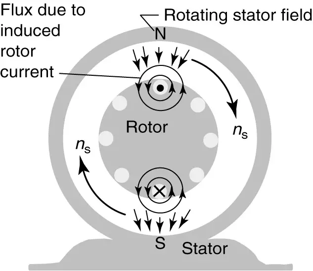
Figure 1: Induction of rotor currents by rotating stator magnetic field.
Consider what happens when the motor is first started. At standstill, when the armature currents are applied, the flux begins rotating in the air gap at synchronous speed. As the North Pole moves past the rotor conductor at the top of the rotor, the conductor cuts the moving lines of flux.
From Faraday’s law we know that any time a conductor cuts lines of magnetic flux, a voltage is induced in the conductor. In this case, the squirrel cage is shorted by the end rings, so the induced voltage will cause a current to flow in the rotor bar.
In Figure 1, the field is moving clockwise, but so far as the rotor conductor is concerned, it is as if the stator field were stationary and the rotor conductor was moving counterclockwise. Thus, by the right-hand generator rule, a current is induced in the top rotor bar in the direction shown (coming out of the page). At the bottom of the rotor, the South Pole is moving and the current induced in the bottom rotor bar is into the page. These induced currents have their own magnetic field, of course, which are shown surrounding the rotor conductors. Note that for the top rotor bar, the flux caused by the current in the rotor bar adds to the stator flux on the left side and reduces the stator flux on the right side. The principle of flux bunching will apply. Because there is more flux on the left side of the conductor, there will be an electromagnetic force on the conductor to the right. The opposite is true for the bottom rotor bar– its force is to the left.
The forces acting on the conductors create a torque on the rotor. If the rotor is free to move (and if the force is enough to overcome friction and inertia), the rotor will begin to turn.
Suppose, however, that the rotor is prevented from turning (this is called a blocked rotor). In that case, the stator flux would sweep by the rotor conductor at synchronous speed, inducing currents in the rotor conductors that have the same frequency as the stator currents. The currents induced in the rotor cause a second rotating rotor magnetic field, which also rotates around the air gap at synchronous speed.
At Blocked-rotor conditions, the induction motor effectively becomes a transformer with the secondary shorted. Thus, it should be no surprise that the starting current is very high for the induction motor.
Three Phase Induction Motor Slip
Now, again assume the rotor is free to turn. As the rotor magnetic field attempts to catch the stator magnetic field, the rotor begins to turn. But when the rotor is turning, the stator flux sweeps by the rotor conductors at a slower relative speed. Thus, as the rotor accelerates, the frequency of the induced rotor currents decreases. At the limit, if the rotor were moving at exactly synchronous speed, the rotor bars would not cut the stator flux and no torque would be produced because no rotor currents would be induced.
Thus, the induction motor must run below synchronous speed to produce torque. The operating speed of the rotor is designated by nr. Because the rotor is moving slower than the stator magnetic field, we say the rotor is “slipping” through the stator field, and we define the slip as:
\[\begin{matrix} s=\frac{{{n}_{s}}-{{n}_{r}}}{{{n}_{s}}} & {} & \left( 3 \right) \\\end{matrix}\]
Where ns and nr are in RPM or revolution per second. Slip is often represented as a percentage:
\[\begin{matrix} s=\frac{{{n}_{s}}-{{n}_{r}}}{{{n}_{s}}}\times 100 & {} & \left( 4 \right) \\\end{matrix}\]
Solving equation 4 for the speed of the rotor:
\[\begin{matrix} {{n}_{r}}={{n}_{s}}\left( 1-s \right) & {} & \left( 5 \right) \\\end{matrix}\]
The overwhelming majority of induction motors are classified as general-purpose motors and operate typically at a full-load slip of less than 5%. Special-purpose induction motors may operate at 15%-20% slip.
Rotor Frequency
Consider the frequency of the induced rotor currents. If you could stand on the rotor and rotate with it, you would see each magnetic pole of the rotating field pass by (ns-nr) times per second. Every time a pole pair passed the conductor you are on, it would induce a cycle of voltage. From equations 2 and 3, if there are P poles the frequency of the rotor currents, fr, would be:
\[\begin{matrix} {{f}_{r}}=\frac{P}{2}\times \left( {{n}_{s}}-{{n}_{r}} \right)=\frac{P}{2}\times \left( s{{n}_{s}} \right)=s{{f}_{s}} & {} & \left( 6 \right) \\\end{matrix}\]
Where fs is the frequency of the stator currents. If you are standing on the rotor, the stator field goes by at sns RPM, so the frequency of the currents in the rotor is sfs.
Induction Motor Example
A six-pole, 60 Hz induction motor operates at 3% slip. At what rate do the stator field, the rotor, and the rotor field revolve? What is the frequency of the rotor currents?
Solution
The synchronous speed of the motor can be calculated from equation 1:
\[{{n}_{s}}=\frac{120\times {{f}_{s}}}{P}=\frac{120\times 60}{6}=1200\text{ }RPM\]
Thus, the stator and rotor fields rotate around the air gap at 1200 RPM. Since the slip is given, we can find the rotational speed of the rotor from equation 5:
${{n}_{r}}={{n}_{s}}\left( 1-s \right)=1200\times \left( 1-0.03 \right)=1164\text{ }RPM$
And the frequency of the rotor currents is given by equation 6:
\[{{f}_{r}}=s{{f}_{s}}=0.03\times 60=1.8Hz\]
Since the rotor is rotating at 1164 RPM and the rotor field is rotating at 1200 RPM (synchronous speed), the field speed with respect to the rotor is given by:
${{n}_{s}}-{{n}_{r}}=1200-1164=36\text{ }RPM$
If you are standing on the rotor, the stator and rotor fields appear to be going around you at 36 RPM. But since you and the rotor are going 1164 RPM, the rotor field is traveling at 1200 RPM, in synchronism with the stator field.
Note that the nameplate does not tell us how many poles the induction motor has. However, by providing us with the operating speed and frequency, we can surmise how many poles it has by using equation 1.
Three Phase Induction Motor Key Takeaways
Understanding the principles of three-phase induction motor such as rotating magnetic fields, synchronous speed, slip, rotor current frequency, and electromagnetic torque generation—is crucial for both theoretical and practical applications. These concepts directly influence how motors are selected, designed, and operated in real-world systems. Induction motors are widely used in industrial automation, HVAC systems, electric vehicles, and household appliances due to their robustness, efficiency, and simplicity.