The article explores the torque-speed characteristics of induction motors, highlighting motor, generator, and braking regions, and their dependence on slip, voltage, and rotor resistance. It details equivalent circuit modeling, torque calculations, and practical implications for motor operation, including starting and breakdown torque dynamics.
Figure 1 showed a plot of induction motor torque vs speed from zero to synchronous speed. This curve is called the torque-speed characteristic curve. We can derive an equation from the equivalent circuit that allows the calculation of the torque for a given value of slip.
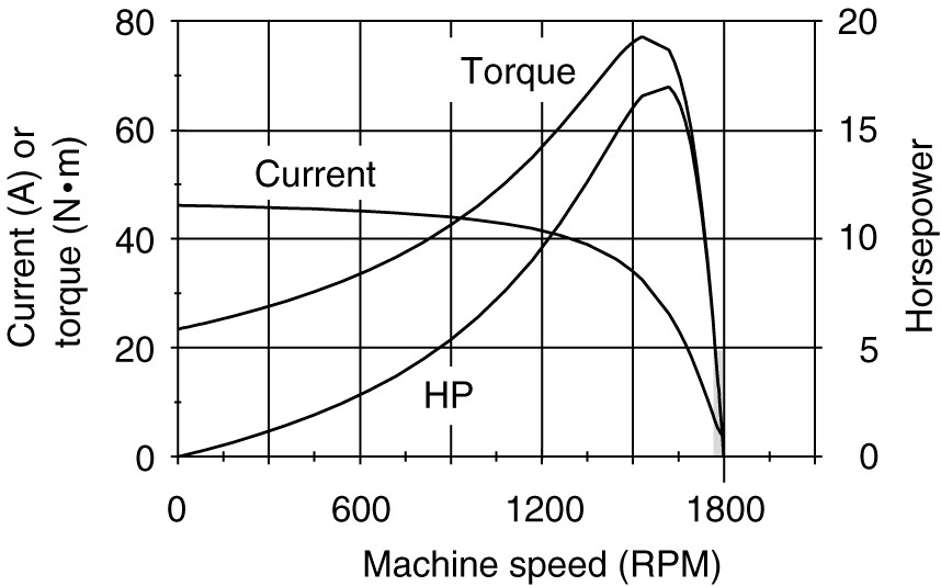
Figure 1. Induction motor torque-speed characteristic curves.
Figure 2 showed the equivalent circuit for the stator. We can simplify our calculations by replacing it with a Thevenin’s equivalent so that we do not have parallel branches in the equivalent circuit. Figure 3 shows a Thevenin’s equivalent of the stator. The Thevenin’s voltage, V1a, is equal to E1 in Figure 2.
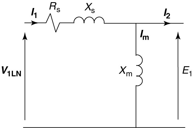
Figure 2. Induction motor stator equivalent circuit.
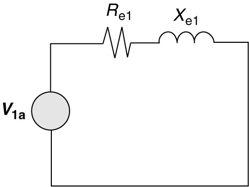
Figure 3. Thevenin equivalent of the induction motor stator.
Referring to the equivalent circuit of the stator and applying voltage division, the Thevenin’s voltage can be calculated as:
\[\begin{matrix} \left| {{V}_{1a}} \right|=\left| {{V}_{1}} \right|\frac{{{X}_{m}}}{\sqrt{R_{s}^{2}+{{\left( {{X}_{s}}+{{X}_{m}} \right)}^{2}}}} & {} & \left( 1 \right) \\\end{matrix}\]
The Thevenin impedance, Re1 + jXe1, is obtained by replacing the voltage source in Figure 2 with a short circuit and then solving for the impedance looking back into the circuit. Looking back into the stator circuit, we find the magnetizing reactance in parallel with the stator winding impedance:
\[\begin{matrix} {{Z}_{e1}}=\frac{\left( {{R}_{s}}+j{{X}_{s}} \right)\times j{{X}_{m}}}{{{R}_{s}}+j\left( {{X}_{s}}+{{X}_{m}} \right)} & {} & \left( 2 \right) \\\end{matrix}\]
Having found the Thevenin equivalent of the stator, we can add the rotor circuit to it. Figure 4 shows the rotor circuit coupled to the Thevenin equivalent of the stator and magnetizing branches. Because this circuit consists of two impedances in series, we can easily calculate the rotor current in terms of V1e (and thus V1). Using the rotor current, we can then calculate the torque directly as a function of the slip.
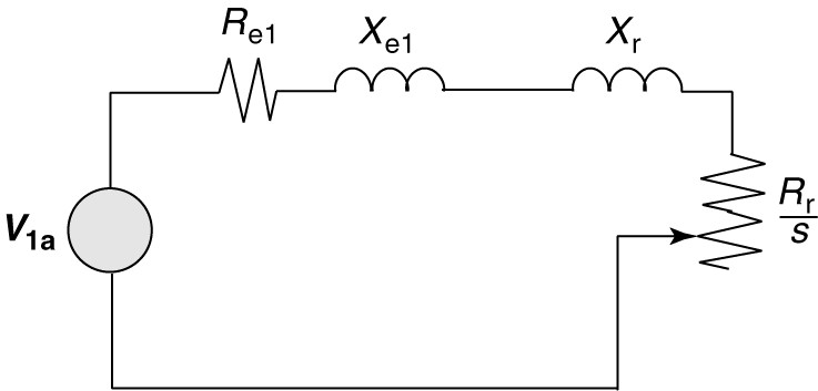
Figure 4. Simplified equivalent circuit for the induction machine.
Clearly, the current will be given by the source voltage divided by the total impedance in the circuit of Figure 4. We are looking to find the torque so we really only need the magnitude of the current, which can be found as
\[\begin{matrix} \left| {{I}_{r}} \right|=\frac{\left| {{V}_{1a}} \right|}{\sqrt{{{\left( {{R}_{e1}}+\frac{{{R}_{r}}}{s} \right)}^{2}}+{{\left( {{X}_{e1}}+{{X}_{r}} \right)}^{2}}}} & {} & \left( 3 \right) \\\end{matrix}\]
Using the current magnitude, we can find the developed power of the machine, which is simply the power dissipated in the variable resistance of Figure 2.
\[\begin{matrix} {{P}_{d}}=3{{\left| {{I}_{r}} \right|}^{2}}{{R}_{r}}\left( \frac{1-s}{s} \right) & {} & \left( 4 \right) \\\end{matrix}\]
From the developed power of equation 4, we can find the developed torque:
\[\begin{matrix} {{T}_{d}}=\frac{{{P}_{d}}}{{{\omega }_{r}}} & {} & \left( 5 \right) \\\end{matrix}\]
Where (ωr=2πnr, and n, is the revolutions per second. Using equations (4) and (5) and recalling the relationship between nr and ns (nr=ns (1-s)) yields:
\[\begin{matrix} {{T}_{d}}=3\frac{{{\left| {{I}_{r}} \right|}^{2}}{{R}_{r}}(1-s)}{s{{\omega }_{r}}}=3\frac{{{\left| {{I}_{r}} \right|}^{2}}{{R}_{r}}}{s{{\omega }_{s}}}\text{ N}\text{.m} & {} & \left( 6 \right) \\\end{matrix}\]
Finally, we can substitute the current of equation 3 into equation 6 to obtain the developed torque as a function of the slip and the machine parameters:
\[\begin{matrix} {{T}_{d}}=3\frac{{{R}_{r}}}{s{{\omega }_{r}}}\times \frac{{{\left| {{V}_{1a}} \right|}^{2}}}{\sqrt{{{\left( {{R}_{e1}}+\frac{{{R}_{r}}}{s} \right)}^{2}}+{{\left( {{X}_{e1}}+{{X}_{r}} \right)}^{2}}}} & {} & \left( 7 \right) \\\end{matrix}\]
From equation 7, we can immediately notice that the torque for a given value of slip is proportionate to the applied voltage squared. Thus, reducing the voltage applied to a motor will cause it to develop substantially less torque, or to operate at a higher value of slip for a given load. As an example, the motor described by the nameplate in Figure 5 is rated at 230/460 V and 1765 RPM. However, it is also rated to operate from a 208 V supply. If one were to operate the motor at 208 V. it would run slower than 1765 RPM if it was fully loaded.

Figure 3. Typical induction motor nameplate information.
Although equation 7 appears formidable, it is relatively simple to program it using a spreadsheet. With the spreadsheet, the slip can be varied over a wide range to obtain the complete torque-speed characteristic. Figure 4 shows the torque of the motor plotted as a function of slip as the slip varies from -1 to +2.
Motor Region
The motor region, which we have already considered, occurs for slip between 0 and 1.

Figure 4. Induction motor torque-speed characteristic.
Generator Region
The slip is negative in the region to the right of the motor region, which implies the rotor is rotating faster than the stator field. This can only occur if the rotor is mechanically driven. The torque in this region is opposite to the direction of rotation, indicating generator action. Induction generators are seldom used because they require reactive power either from the power system or from an external capacitor bank. The induction generator, however, does not have to operate at only one speed like the synchronous machine and is thus useful for applications where the speed of the machine will vary. One such application is for wind generators.
Braking Region
The region to the left of the motor region in Figure 4 is one in which the slip is greater than 1, which implies that the rotor is rotating in the opposite direction of the stator field. Because the torque is positive and in the direction of the stator field, it opposes the rotor’s motion, causing the rotor to quickly slow down. Thus, this is called the braking region. This is done by switching two of the leads on the three-phase supply to the stator. Braking is used when it is necessary to stop the motor very quickly; however, braking is very hard on the motor as the currents during braking are very high, causing heating of the windings. The stored energy of the rotating rotor is also dissipated in the form of heat.
| Region | Slip (s) | Description |
| Motor Region | 0<s<1 | Rotor rotates slower than the synchronous speed; torque aids rotation for mechanical power output. |
| Generator Region | s < 0 | Rotor rotates faster than the synchronous speed; torque opposes rotation, enabling generator action. |
| Braking Region | s>1 | Rotor rotates in the opposite direction to the stator field; torque opposes motion, causing rapid deceleration. |
The motor region of the torque-speed curve
The accuracy of the induction motor model has limitations, and the actual torque-speed characteristic is somewhat more complicated than the model predicts. Figure 5 shows the torque-speed characteristic as it might actually appear. For many induction motors, the average torque drops a bit as it accelerates and then rises to a peak value of torque, known as the pull-out or breakdown torque. The normal operating region for the induction motor is the nearly linear portion between rated speed and synchronous speed, shown by the heavy line. Note that the negative slope of the operating region provides stable operation, because an increase in load slows the machine down, causing the motor to develop more torque.

Figure 5. Induction motor torque-speed characteristic.
The maximum torque that the motor can produce is called the breakdown torque. The motor cannot operate in the steady-state at speeds below the breakdown torque. Operation in that region occurs only during starting or if the motor is overloaded to the point of stalling out.
Operation at speeds between the breakdown torque and rated-speed means that the motor is overloaded, which should be limited to short periods in accordance with the motor manufacturer’s recommendations.
Several important values of torque associated with the torque-speed characteristic are shown in Figure 6. The starting or locked rotor torque must be larger than the torque required by the load at zero speed in order for the motor to start.
Some loads, like a fan blade, require very little torque to start, but others, like a loaded conveyor belt, may require starting torque in excess of the full-load torque.
During the acceleration of the motor, the motor torque must always be greater than the torque required by the load, otherwise, the motor will stall. Thus, it is important to know the minimum value of torque during the acceleration, which is called the pull-up torque.
The maximum torque that the motor is capable of producing is called the pullout or break-down torque. If the load is increased beyond the breakdown torque, the motor will decelerate and stall. Once stalled, it would draw the starting current causing it to burn up, unless the motor is properly protected against overcurrents. Since we have an algebraic expression for the torque as a function of slip, we can determine what the maximum torque will be and at what speed it occurs.
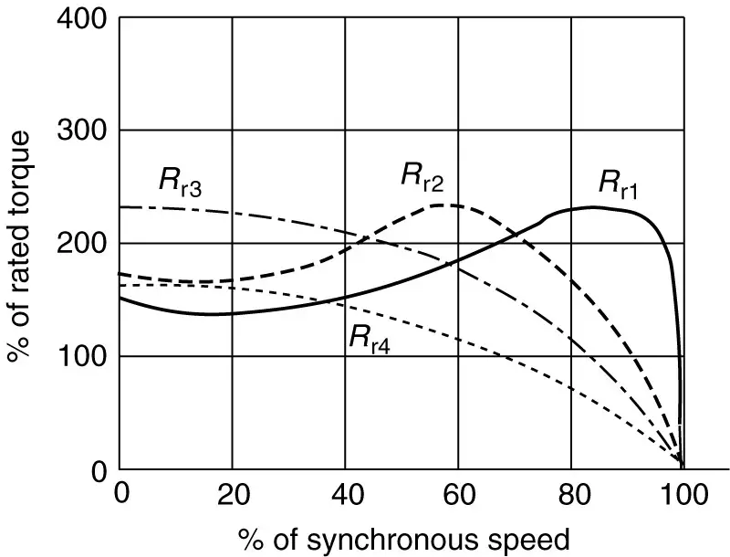
Figure 6. Effect of varying rotor resistance on the induction motor torque-speed curve.
Breakdown torque
Equation 7 expresses the developed torque as a function of the slip, and as shown by the plot in Figure 4, the torque has a maximum value. We can find the maximum value by taking a partial derivative of torque with respect to slip and setting the resulting expression equal to zero. Following that procedure would yield the following expression for the maximum developed torque:
\[\begin{matrix} {{T}_{\max ,dev}}=\frac{3}{2{{\omega }_{s}}}\times \frac{{{\left| {{V}_{1a}} \right|}^{2}}}{{{R}_{e1}}+\sqrt{R_{e1}^{2}+{{\left( {{X}_{e1}}+{{X}_{r}} \right)}^{2}}}} & {} & \left( 8 \right) \\\end{matrix}\]
Where Tmaxdev is the maximum developed torque. Similarly, we could find the slip at which the maximum torque occurs:
\[\begin{matrix} {{s}_{mt}}=\frac{{{R}_{r}}}{\sqrt{R_{e1}^{2}+{{\left( {{X}_{e1}}+{{X}_{r}} \right)}^{2}}}} & {} & \left( 9 \right) \\\end{matrix}\]
Several observations can be made from equations 8 and 9.
- First, the slip at maximum developed torque, smt, is directly proportionate to the rotor resistance, Rr.
- Second, the maximum developed torque is independent of the rotor resistance.
- The third observation is, as we noted earlier for torque, the maximum developed torque is proportionate to the applied voltage squared.
These observations have an important role for the operation of induction motors, particularly when we deal with starting them.
The independence of torque with respect to it rotor resistance is particularly important for wound-rotor induction motors. By placing a resistance in the rotor circuit, we can limit the starting current while increasing the starting torque. Figure 6 shows what happens qualitatively. As the resistance is increased in the rotor circuit, the slip at which the pullout torque occurs gets larger. If we have a switchable bank of resistance in the rotor circuit, we can keep the machine near its maximum torque as it accelerates by decreasing the resistance in steps.
Induction Motor Torque Speed Key Takeaways
Understanding the torque-speed characteristics of induction motors is essential for their effective application in real-world scenarios. These characteristics define how the motor behaves under varying load conditions, enabling engineers to predict performance during starting, normal operation, and overload situations. The motor, generator, and braking regions provide insights into how induction machines can be used not only for driving mechanical loads but also for energy regeneration and controlled stopping. The equations derived from the equivalent circuit, especially with the use of Thevenin’s simplifications, allow for accurate calculation of torque based on slip and other machine parameters. These models are crucial for designing reliable motor control systems, ensuring energy efficiency, and preventing motor damage due to overcurrent or stalling.