The article provides an overview of various types of industrial switches, including push button, limit switches, selector switches, pressure switches, flow switches, and float switches. It outlines their working principles, key components, and general applications in control systems.
Industrial Push Buttons
Push buttons, shown in figure 1, are the most common type of control devices found in industrial facilities. Almost all industrial machines contain push buttons even if the facilities operation is to set to run automatically. Typical push buttons are momentary meaning they are designed with a spring to keep the button contacts open or closed at all times. Some push buttons are designed with a toggle action, once they are set into a position it will require someone to pull or push on it to change its contact state.
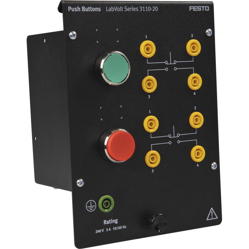
Figure 1: Push Button
Push Button Switch Working Principle
Push buttons are simple single pole switches. They contain a set of contact plates that make or break when activated by someone. All push buttons are made the same way, what gives them their special characteristics or function is the legend plate and sometimes the operator or button head. The legend plate surrounding the push button lets the user know the purpose of the control device, whether it is to turn something on or off or move something up or down, it all depends on what the label is telling the user of the push button to do. In some instances, the shape of the push button indicates its function. For example, a push button in the shape of a mushroom and red in color informs the user that the intention of the push button is to serve as an emergency stop, as shown in figure 2, unlike a push button that is simply red to indicate stop and/or green to indicate start.
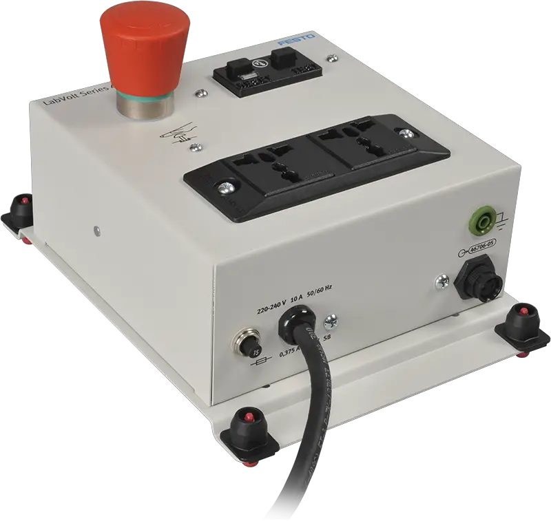
Figure 2: Emergency Stop Button
Push buttons are designed to function the same way but they are equipped with different operators. An operator is the part of the device that is pushed, pulled or rotated by someone operating the circuit. Most operators of push buttons are covered by shrouds to prevent dust and dirt from entering the control device.
- You May Also Read: Proximity Sensor Working Principle | Inductive Proximity Sensor | Capacitive Proximity Sensor
Push Button Contact Block
A contact block, as shown in figure 3, is part of the control device that is activated by the operator. Contact blocks contain metallic alloy often called points that are great for conducting current. Some control devices contain one normally open or normally close set of contacts while others contain a combination of normally open and normally closed contacts and then there are those that contain two or more normally open and normally closed contacts. Multiple contacts can be added or changed out to the operator as desired.
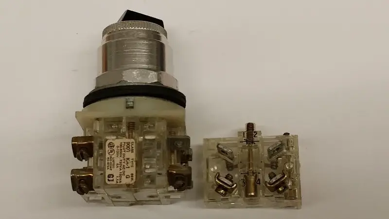
Figure 3: Contact Block
Contact blocks can be replaced if necessary. The reason for replacing the contact blocks occur when the arcing effects that occur within the block. This takes place due to short-circuit and high current affecting the contacts that become pitted, distorted or welded together rendering the control device useless.
Push buttons should be installed into control panels or push button stations for safe and secure operation. When installing or replacing push buttons it is important to pay close attention to the size of the push button because push buttons are different sizes and shapes.
Limit Switch Working Principle
A limit switch, as seen in figure 4, is an electrical mechanical device installed in many operations to sense physical presence of objects. Limit switches are designed with many types of operators and contact blocks. Operators such as cams and levers make up the design of the limit switch. This enables limit switches to fit any environmental or physical configuration it needs to be installed in. Limit switches come designed with single contacts, normally open and normally closed or a combination of both, this is done to allow the limit switch to be installed in all types of direct and to fit any operation. Some limit switches can be installed on mounting plates while others are in connected to raceways with a connector.
Application of Limit Switch in Industry
When selecting a limit switch it is important to select the limit switch that will be able to carry the current of the load served. A limit switch to turn on a motor would be required to carry high current so the contacts would be rated for a large amp value: which means that the limit switch would have to be of a heavy duty type construction. A limit switch used to send a signal to a PLC or to turn on a contactor or motor starter of a control system can be very small and the contact blocks would be designed to serve medium or light duty actions.
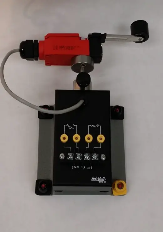
Figure 4: Fig.4: Limit Switch
Selector Switch Working Principle
A selector switch, as seen in figure 5, is a control device used to toggle functions instead of using momentary contacts like a pushbutton. A selector switch operator is designed so the user can turn the switch from left to right or it is designed to push the selector switch left or right or up in down. Selector switches come in two types, the two position, and the three position design. The two position selector switch has two sets of contacts which mean one set of the contacts in the switch is always connected. The two position selector switch legend plate can only indicate two functions such as off and on, run and jog, or forward and reverse. The three position selector switch has a contact block containing two sets of contacts that also contain a position that will allow the operator to be placed in a neutral position or off. This means the selector switch can control two separate loads but only one load at a time or both loads can be off at the same time. Selector switches data sheets come with a truth table to indicate the connection of the contacts this helps the user to identify the combination connection points of the selector switch.
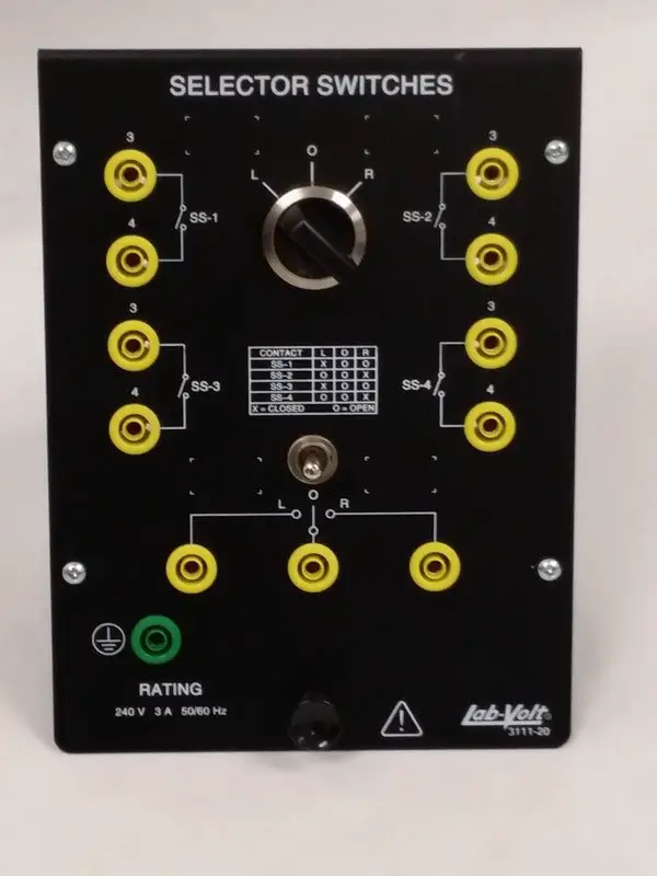
Figure 5: Selector Switch
Pressure Switch Working Principle
A pressure switch is a device that detects a certain amount of force, shown in figure 6. Once the set point is reached the electrical contacts will change their state from normally open to normally closed or from normally close to an open position. Some pressure switches are connected to two different pressure switches to provide differential sensing.
Figure 6 (a): Typical Pressure Switch
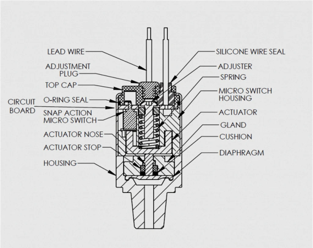
Figure 6 (b): Pressure Switch Circuit Diagram
Pressure Switch Types
Pressure switches come in three main types: bellows, diaphragm, and piston designs. The Bellows Pressure Switch is a cylindrical device with several deep folds that expands and contracts as pressure is applied. One end of the bellows is sealed and the other is connected to the source of the pressure. As pressure changes it causes the adjustable spring tension to move changing the state of the contacts.
The next design is the Diaphragm Pressure Switch which is a deflecting mechanical operator that moves when force is applied to it. One side of the diaphragm is connected to the pressure source and the other side is for venting out. The spring tension of the diaphragm pressure switch is adjustable to allow different pressure settings, however, they are only used for pressures up to 200 PSI.
The Piston Pressure Switch design is made for very high pressures. The shaft of the piston is sealed in a stainless steel cylinder for smooth operation. When pressure is applied to the piston it moves and changes the state of the contact. Like the bellows and diaphragm, the piston also contains an adjustable spring tension to be set for different pressure systems.
Pressure Switch Components
Pressure switches have two major components that users and technicians should be aware of. First, the pressure switch has a dead band which is the amount of travel the switch must go through before the contacts change their state. Second but most importantly a pressure switch should never be overridden. Pressure switches act as a safety control device. Once the technician performs a jump out or force the contacts into an operating position pressure can continue to build and there’s no mechanism for shutting it off, serious consequences can be the result of poor decision making on behalf of the technician. A poor decision could lead to loss of life or limb.
Flow Switch Working Principle
A flow switch is a control device that detects the movement of liquid, as seen in figure 7. Flow switches are installed via pipes to prevent problems in pumping systems due to clogging. Clogged pipes in a flow system can result in cavitation which is violent shaking of the pipes or cause a lack of performance in the system it is intended to operate. The function of the flow switch installed in a pipe is to detect the abscesses of force on the spring tension paddle, when there is no liquid flowing, the contacts will open the control system turning off the pump motor to prevent damage being done. More advanced flow switches use wireless communication connected to the control system for monitoring flow rate and contact state.
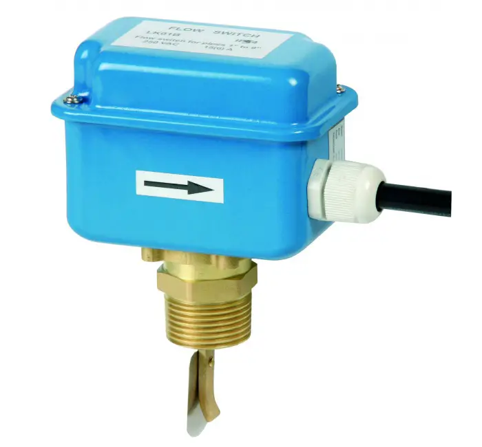
Figure 7 (a): Flow Switch
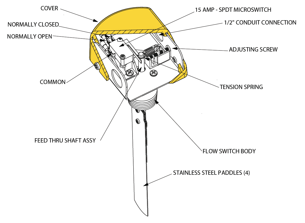
Figure 7 (b): Flow Switch Circuit Diagram
Float Switch Working Principle
A level or float switch is a device used to detect the height of liquids and solids. Level switches can be found anywhere from residential units to industrial plants, as seen in figure 8. The level switch is the device in the tank of the toilet that turns the water off once the reservoir tank fills with water. In industrial plants level switches are used in mixing tanks, vessels, reservoirs, and other containers with material must be controlled. Level switches work like many of the devices discussed previously in which the operator of the device is activated by an outside force causing the electrical contacts to change their state.

Figure 8 (a): Float or Level Switch
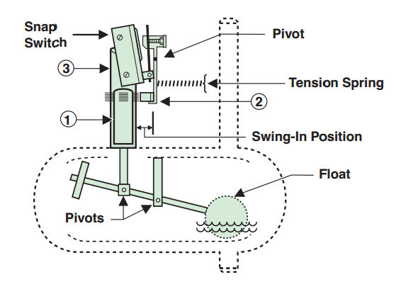
Figure 8 (b): Level Switch Circuit Diagram
There are several factors that determine the type of float switch needed. Such factors include motion, hazardous environment, and density of the material, physical state, conductivity, and sensing distance. Each factor determines if there is a need to have a flow switch that is mechanical, magnetic or inductive or capacitive or optical, or ultrasonic.
Push Button Switch Types and Circuit Diagram Key Takeaways