Learn about on and off delay timers, their timing diagrams, and contact symbols to understand their applications in control systems and how they introduce timing delays for effective circuit operation.
What are Time Delay Relays?
Some or all industrial control systems need timing operations. Timing devices are used to cut on or off pilot devices at a preset time. Time delay relays and solid-state timers similar and are used to provide the desired delay and timing functions.
Timers are constructed with dials, displays, or some type of operator interface used to set the time and contact state to normally open or normally closed on the device. Though there are many types of timers and different functions they can perform they all come from two basic types timing functions which are the ON Delay Timer and OFF Delay Timer.
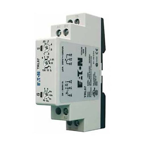
Figure. Time Delay Relay
ON Delay Timer Operation
The on-delay relay timer provides a change to the state of the contacts that are controlled by the energizing of the timer. The on-delay relay timer can be set or programmed to a predetermined time and this is called the preset time. Preset time can be as low as milliseconds to hours and even days but usually, in the industrial control system, it is set to seconds and minutes.
Once the coil of the timer is energized the timer starts to count from zero to the pre-set time, this count is known as the accumulated time. When the preset time and accumulated time are equal the contacts of the timer change their state; contacts that are normally open when the coil was not energized go closed and contacts that are normally closed will change to open. The contacts of the timer will stay in their changed state for the same amount of time the coil is energized. When the power is removed from the coil of the timer the accumulated time returns to zero and contacts return to their original state.
Timing diagrams are usually used to illustrate the operation of the timers’ function, so there will be a little learning curve to understanding the timers function.
- You May Also Read: Solid State Timer | Solid State Relay Timer
On Delay Contact Symbol
On-delay timers can easily be identified in ladder diagrams. On-delay timer coils are represented like all loads illustrated ladder diagrams except there is a label with the abbreviation of TD which stands for time delay and the contacts are drawn like a single pole switch with two legs coming out of the bottom as seen in figure 1.
The contact will be either a normally closed or a normally open contact. The normally open contact is termed normally open time close (NOTC) while the normally closed contact is termed normally close timed open contact (NCTO).
On Delay contacts do not have a set of instantaneous contacts ( which means the contacts will change state immediately when the coil of the timer is energized). Not having this operation means the timer cannot be activated by momentary control devices without the use of a control relay which is a pilot device with instantaneous contacts. When the momentary control device is activated the control relay can be used to seal in the circuit and keep the coil of the on delay timer energized for the necessary time period.
Figure 1: NOTC ON Delay Contact
ON Delay Timer Timing Diagram
A timing diagram is a graph that shows the status of the timer to the timing device in relation to the performance of the contact or output of the timer. The diagram has two graphs, one is used to represent the input signal to the timing device; fowling graphic lines are used to represent the timing devices outputs or contacts. The graphic lines in a timing diagram are drawn to show a false to true, on to off, or high to low. The lines are drawn at right angles to represent discrete values of the time cycle because there is no in between the values can only be off or on.
Figure 2: Normally Open Timed Closed (NOTC)
Figure 2 is the timing diagram used to represent a normally open timed closed delay contact. When the timer coil receives power the preset time starts to count. Once the accumulated time has equaled the preset time the timer contact will change from normally closed to open and will remain open until the timer coil has lost power. At this time the timer has been reset back to zero and the cycle can begin again.
Figure 3: Normally Close Timed Open (NCTO)
Figure 3 timing diagram is used to represent the normally closed timed open contact. In this diagram, the load connected to the timer contact is on and will stay on after the timer coil has been energized and the preset time has become equal to the accumulated time. At that point of time, the contact will open causing the load to turn off and stay off until the timer coil has been de-energized. Once de-energized, the timer coil will return to zero and be ready to cycle again.
OFF Delay Timer Operation
Like on-delay timers, off-delay timers can be easily identified. The off-delay timer coil is labeled the same way as other loads are identified in ladder diagrams with the exception of the abbreviation of TD to indicate time delay. The contacts of the off-Delay look like a single pole switch with an arrow pointing down from the switch. The normally open off delay contact is called normally open time open and the normally closed is called normally closed time close contacts. The reason for the opposite operation is because the off-delay contacts are instantaneous. Once the coil of the off-delay timer is energized the contacts immediately change their state. The off-delay coil is energized in a control circuit but the counting will not be started.
The off-delay count does not start until the power has been removed from the coil. Once the coil has been de-energized the time will begin to elapse and when the accumulated time is equal to the preset time the contacts of the off delay will go back to their normal state.
OFF Delay Timer Timing Diagram
The off delay timing diagram can be interpreted in the same manner as the on delay timing diagram. The important factor to remember when interpreting the off delay timing diagram is to remember that an off delay timer contains instantaneous contacts.
Figure 4: Normally Closed Time Closed Off Delay Contact (NCTC)
Figure 4 timing diagram is used to represent the normally closed contact of an off delay timer. The load connected to the normally closed contact will be on before the timer coil is energized. Once the timer coil has been energized the contact will immediately go open causing the load to turn off and remain off until the coil has been de-energized and the preset time has elapsed.
Figure 5: Normally Open Timed Open OFF Delay Contact (NOTO)
Figure 5 timing diagram is used to represent the normally open timed open off delay contact. In the graph, the timer coil is energized and the contact the load is connected to is open. When the timer coil is energized the contact will immediately close turning on the load connected to the contact. The load will stay on after the timer coil has been de-energized until the pre-set time equals the elapsed time then the load will turn off.
Key Takeaways of Time Delay Relays
- Time delay relays are employed to introduce a specific delay in the function of electrical circuits, allowing for control and timing functions.
- They offer precise and adjustable timing capabilities, allowing for applications like delayed start, timed shutdown, or sequence control.
- Time delay relays propose flexibility and reliability in numerous industries, including automation, HVAC systems, motor control, and process control.
- Understanding the fundamental parameters of time delay relays, such as timing range, delay accuracy, and contact ratings, is vital for picking the suitable relay for specific applications.
FAQs on Time Delay Relays
What is a time delay relay and what is its purpose?
A time delay relay is an electrical device used to introduce a time delay in the operation of a circuit. It allows for control and timing functions, such as delayed activation or deactivation of electrical loads.
How does a time delay relay function and what are its key components?
A time delay relay typically consists of a timing mechanism, a control circuit, and switching contacts. The timing mechanism can be based on electromechanical or electronic principles, and it controls the opening or closing of the switching contacts based on the predetermined time delay.
What are the different types of time delay relays available?
There are various types of time delay relays, including on-delay relays, off-delay relays, interval relays, and repeat cycle relays. Each type has its specific functionality and is designed for different timing requirements.
What are the typical applications of time delay relays in electrical systems?
Time delay relays find applications in various industries and systems. They are commonly used in motor control circuits, lighting control systems, HVAC equipment, industrial automation, and process control systems. They provide functions like motor sequencing, pump control, time-based switching, and safety delays.
How do I select the right time delay relay for my application?
When choosing a time delay relay, consider factors such as the necessary time delay range, contact rating, input voltage, and the specific application requirements. It’s important to consult the manufacturer’s specifications and guidelines to ensure compatibility and optimal performance.
Note: The answers provided are general and may vary depending on the specific make and model of the time delay relay.