The article provides an overview of motor contactor and motor starter, explaining their types, working principles, and selection criteria. It also distinguishes between manual and magnetic variants and highlights their roles in controlling and protecting electrical loads.
Motor Contactors and Motor Starters are pilot devices used to control large current loads. Large current loads such as heaters, parking lot lights, and electric motors require a large amount of current during startup. To avoid exposing the operator and light-duty control devices, such as common household light switches to these high currents, contactors and motor starters are used. Contractors, as seen in Figure 1, and motor starters, as seen in Figure 2, are directly connected to the loads to be controlled like a high-powered lamp or a three-phase industrial motor. A control device or control system is used to control the contractor or the motor starter.
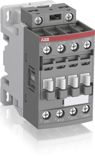 Figure 1: Motor Contactor

Figure 2: Motor Starter with Electronic Overloads
Contactor and Motor Starter Working Principle
Contactors and motor starters contain a coil of wire wrapped around a soft iron core. When the voltage is applied to the coil of the pilot device an electromagnetic field is created. This electromagnetic field is used by the pilot device to cause the on and off operation of the loads. The current used to energize the coil is far less than the current needed to operate the load. This indicates that the load may draw 30 amp on start up in the contactor or motor starter but it will be controlled by a current that is only about .2 A or 200 mA. It is safer to work with low current versus working with a high current that can potentially harm the operator or the equipment.
Contactor and Motor Starter Rating and Size
Contactors and motor starters come in many sizes and ratings to accommodate a wide variety of applications and operations. The applications can range from a starter, which is used to turn on a drill press to a contactor that is used to operate an electric boiler. It is important to know that not just any size contactor or motor will suffice as a way to operate loads; when working with contactors and motor starters maintenance technicians and installers must observe guidelines to installing pilot devices. One important guideline to know is the amperage of the load served. This will determine the selection of the correct NEMA (National Electrical Manufacturing Association) or IEC (International Electro-technical Coalition) size pilot device. It is important also to know the environment which the device will be installed. This will ensure that the correct enclosure can be selected to avoid any disruption in the service of the pilot device. Though these pilot devices perform the same job, they cannot perform the same duty.
Motor Contactor
The following section includes a detailed discussion about contactors. Contactors come in two varieties: manual and magnetic designs. Manual contactors and motor starters are designed for medium to low current load operations where it is safer for the operator to be in close proximity to the load that is needed to be turned on and off. Magnetic contactors and motor starters are used in automation and remote control of loads that may carry too much current to safely operate.
Manual Contactor Working Principle
Manual contactors are a pilot device used to operate loads that do not need overload protection like heating elements or they operate loads that have overload protection internally designed such as single phase AC motors. Manual contactors are constructed with a on and off toggle switch to operate loads connected to it, this means it requires someone to physically press the push button to energize the loads. Manual contactors are better suited for medium duty loads because the contacts built inside the units are able to carry a large amount of current for a long period of time, versus a regular switch that is rated for lower current operations and cannot handle a large amount of current over long periods of time.
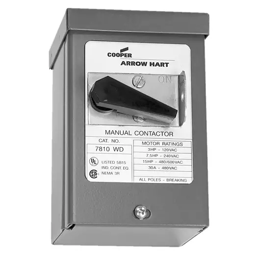
Figure 3: Manual Motor Contactor
Magnetic Contactor Working Principle
Magnetic contactors, as seen in Figure 4, contain a solenoid which is a coil of wire wrapped around or surrounded by an iron core. The magnetic contactor operation requires two voltage sources; one source is to facilitate the operation of the load (such as heaters or machine tools). The second voltage needed is to control the operation of the solenoid known as the control voltage. The control voltage is usually lower than the electrical power circuit and is derived from the control transformer. The typical voltage used to control the solenoid is 24 V DC to 120 V AC but other voltages can be used, depending on the design, preference, and the situation.
Figure 4: Magnetic Motor Contactor
Magnetic Contactor Rating Selection
Magnetic contactors are selected based on the amperage rating. The amperage rating is the amount of current the silver alloy contact uses to safely carry and transmit the electrical power without causing damage to the contactors or electrical wiring.
Magnetic Contactor Types
Contactors also come in different physical configurations. Contactors can have one set of contactors for a single phase operation in which one hot conductor can make or break through the contactor or two sets of contacts to make or break two hot conductors in a single phase operation. Contactors can have as many as four sets of contacts that are normally open but can be changed to normally close to suit a particular order of operation. All magnetic contactors contain a solenoid that has two terminals which are important to locate to achieve proper operation of the contactor. The solenoid voltage must match the control voltage, too much voltage will cause the solenoid to burn up, and as a result, the contacts will not be able to open or close. When there is too little voltage, the contactor will not work because the magnetic field is not strong enough to pull the armature in.
Motor Starter
There are two types of motor starters used in industry; they include the manual motor starter and the magnetic motor starters. Each starter performs the same function which is to make or break the line power serving the load connected to the pilot device and provide the loads’ overload protection. The difference between the manual and magnetic motor starter is the manner in which they control the action of making and breaking the supply power to the loads.
Manual Motor Starter Working Principle
A manual starter, as seen in Figure 5, is a contactor that does not include a coil and acts more like a switch than a contactor. The manual motor starter is constructed with an operator that can include a selector switch or a set of push buttons that open and close the contacts of the pilot device. The name manual motor starter means it requires someone to operate the contacts but the overload contacts of the manual motor starter automatically control the load; should it overheat due to mechanical failure or high ambient temperatures.
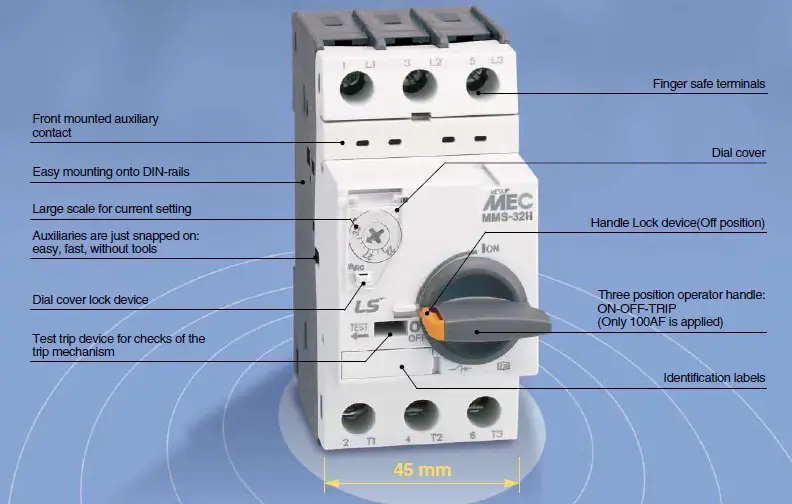
Figure 5: Manual Motor Starter Schematic
Magnetic Motor Starter Working Principle
Magnetic motor starters, as seen in Figure 6, are magnetic contactors with an overload package connected to the terminal side of the pilot device. The magnetic motor starter is more commonly used because it can be used in operations that require automatic control of the load and the magnetic contactor can be remotely activated with control devices or with a complex of control device operations.
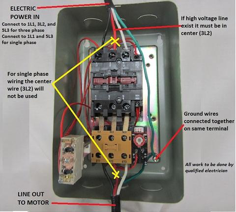
Figure 6: Magnetic Motor Starter Wiring Diagram
A magnetic motor starter has three line terminals labeled L1, L2, and L3. This is where the power terminates to the motor starter. The terminals at the bottom of the motor starter are labeled T1, T2, and T3 which is also referred to as the load side that connects to the load served. In order to turn the load on and off, the coil must be connected to the normally closed overload contact which is usually connected by way of a factory wire installed on the unit. The normally closed contact is not considered an auxiliary contact; therefore, it cannot be used for anything else in the control circuit. The magnetic motor starter also contains a normally open auxiliary contact that will connect to the control system which enables the energizing and de-energizing of the magnetic coil. The auxiliary contacts will have one side connected directly to the terminal of the magnetic coil which is sometimes connected to field devices that toggle the operation of the magnetic coil When using momentary control devices to control the load connected to the magnetic motor starter, the opposite auxiliary normally open contact is used to provide a seal-in for the coil of the pilot device. When the seal-in is used this is referred to as a three-wire control operation of the motor starter. When the seal-in is not used it is called a two-wire control.
Motor Starter Types Key Takeaways
Understanding the function, types, and operation of motor contactors and motor starters is crucial for ensuring the safe and efficient control of electrical loads in industrial and commercial applications. These pilot devices help manage high inrush currents, protect equipment from overloads, and facilitate remote or automated control, minimizing human exposure to dangerous electrical conditions. Whether used in controlling heavy machinery, lighting systems, or heating elements, the proper selection and application of manual or magnetic contactors and starters directly impact system reliability, safety, and operational performance.