In this section, we’ll review the operating characteristics of basic delta-delta, wye-wye, delta-wye and wye-delta connections of the transformer.
The construction of a three-phase transformer can be represented as shown in Figure 1. The shell type core has three sets of primary and secondary windings. How these windings are connected together determines the configuration of the transformer (delta, wye, etc).
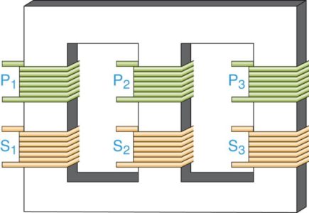
Figure 1: Three-Phase Transformer Construction
Wye-Wye (Y-Y) Connected Transformer
The transformer in Figure 1 can be represented as shown in Figure 2. T1, T2, and T3 represent the same three primary/secondary coil pairs shown on the shell type core. The lines labeled ΦA1, ΦB1 and ΦC1 represent primary line conductors that connect to the primary coils, and the line labeled N1 represents a neutral conductor. Likewise, the lines labeled ΦA2, ΦB2 and ΦC2 represent secondary line conductors and N2 represents a neutral conductor.
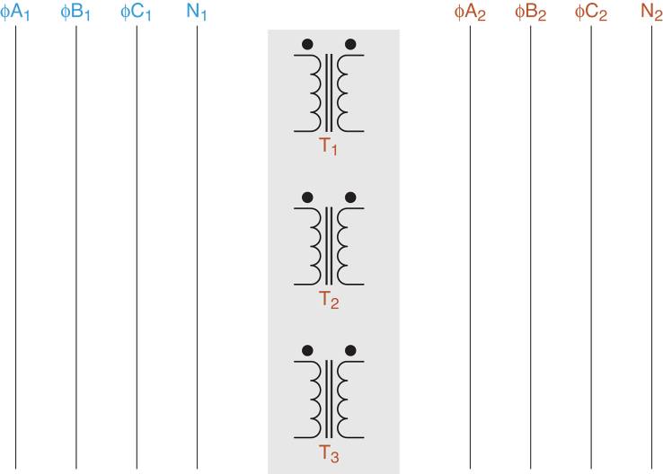
Figure 2: Elements of a transformer wiring diagram.
When wired as shown in Figure 3, the shell type transformer forms a Y-Y (wye-primary-wye secondary) circuit. As such, the transformer primary and secondary current and voltage relationships are as follows:
$\begin{matrix}{{E}_{L}}=\sqrt{3}\times {{E}_{P}}=1.732\times {{E}_{P}} & {} & {{I}_{L}}={{I}_{P}} \\\end{matrix}$
$\begin{matrix}{{E}_{P}}=\frac{{{E}_{L}}}{\sqrt{3}}=\frac{{{E}_{L}}}{1.732} & {} & {{I}_{N}}={{I}_{A}}+{{I}_{B}}+{{I}_{C}}=0 \\\end{matrix}$
Where EL and IL are the line values, and EP and IP are phase values. These relationships assume that the Y-Y circuit is balanced (Before reading on, take a moment to trace out the circuit connections in Figure 3 to verify that the diagram represent the same circuit).
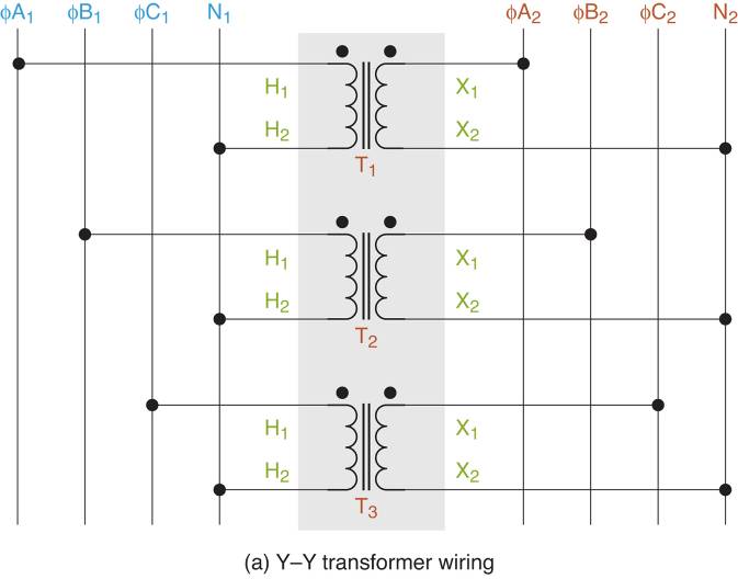
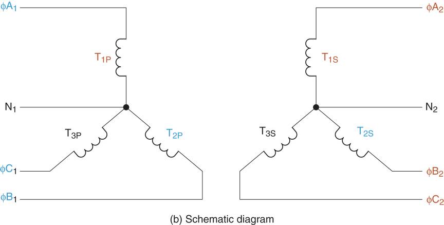
Figure 3: Y-Y transformer Schematic & Wiring Diagram
There are two points to be made:
• The wiring diagram in Figure 3a can be made implemented using a bank (group) of three single phase (1Φ) transformers.
• Y-Y Transformers are used in industrial applications and are preferred over ∆-∆ transformers when it is critical to have a neutral connection in the secondary circuit.
- You May Also Read: Three Phase Transformer Connections Phasor Diagrams
Delta-Delta (∆-∆) Connected Transformer
When wired as shown in Figure 4, the shell type transformer forms a ∆-∆ (delta primary-delta secondary) circuit. Note that there is no neutral line in the wiring diagram. The transformer, primary and secondary current, and voltage relationships are as follows:
$\begin{matrix}{{E}_{L}}={{E}_{P}} & {} & {{I}_{L}}=\sqrt{3}\times {{I}_{P}}=1.732\times {{I}_{P}} \\\end{matrix}$
$\begin{matrix}{{I}_{P}}=\frac{{{I}_{L}}}{\sqrt{3}}=\frac{{{I}_{L}}}{1.732} & {} & {{I}_{N}}={{I}_{A}}+{{I}_{B}}+{{I}_{C}}=0 \\\end{matrix}A$
Where EL and IL are line values, and EP and IP are phase values. These relationships assume that the ∆-∆ the circuit is balanced (Before reading on, take a moment to trace out the circuit connections in Figure 4 to verify the diagrams represent the same circuit).
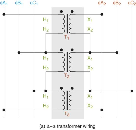

Figure 4: Delta-Delta (∆-∆) Transformer Schematic & Wiring diagrams.
As was the case with the Y-Y circuit, the wiring diagram in Figure 4a can be implemented using a bank of single-phase transformers. Note that ∆-∆ transformers are most commonly found in Industrial applications.
Wye-Delta (Y-∆) Connected Transformer
When wired as shown in Figure 5, the shell type transformer forms a Y-∆ (wye primary-delta secondary) circuit. Note that there is a neutral connection in the primary circuit, but none in the secondary circuit. (Before reading on, take a moment to trace out the circuit connections in Figure 5 to verify that the diagrams represent the same circuit).
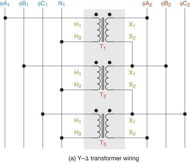
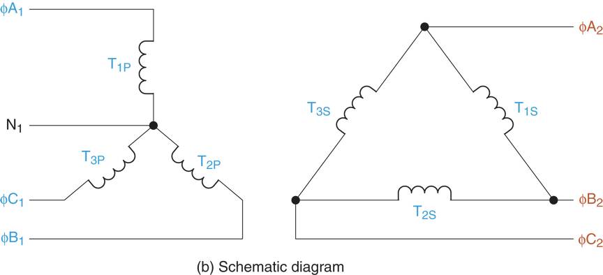
Figure 5 Wye-Delta (Y-∆) transformer Schematic & Wiring diagrams.
As was the case with the previous circuits, the wiring in the diagram in Figure 5a can be (and often is) implemented using a bank of single phase (1Φ) transformer. Note that Y-∆ connected transformers are most commonly used in high voltage transmission system.
Delta-Wye (∆–Y) Connected Transformer
When wired as shown in Figure 6, the shell type transformer forms ∆-Y (delta primary-wye secondary) circuit. Note that there is a neutral connection in the secondary circuit, but none in the primary circuit. (Before reading on, take a moment to trace out the circuit connections in Figure 6 to verify that the diagram represents the same circuit).
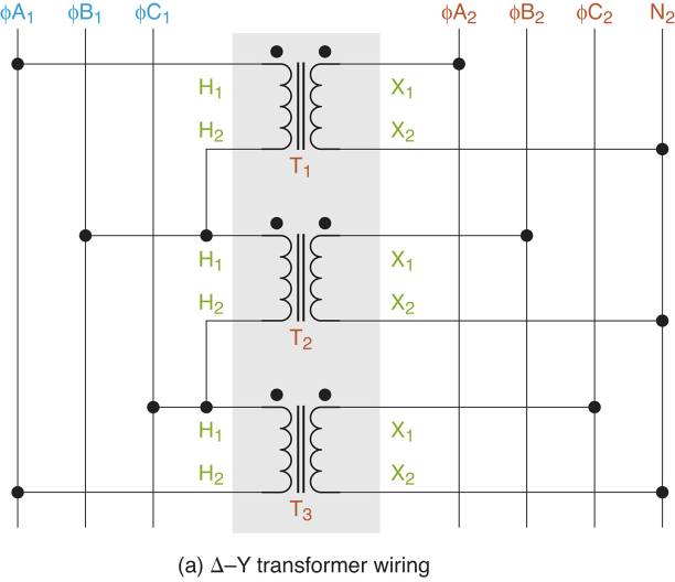
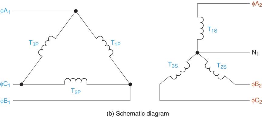
Figure 6 (Delta-Wye )∆-Y transformer Schematic & Wiring Diagram
As was the case with the previous circuits, the circuit in Figure 6a can be implemented using a single phase (1Φ) transformers. Note that ∆-Y connected transformers are most commonly found in commercial and industrial applications.
Why Using Single Phase Transformer Banks?
As mentioned earlier, each transformer introduced in this section can be constructed using a bank (group) of single-phase transformers. Such a transformer bank is shown in Figure 7.
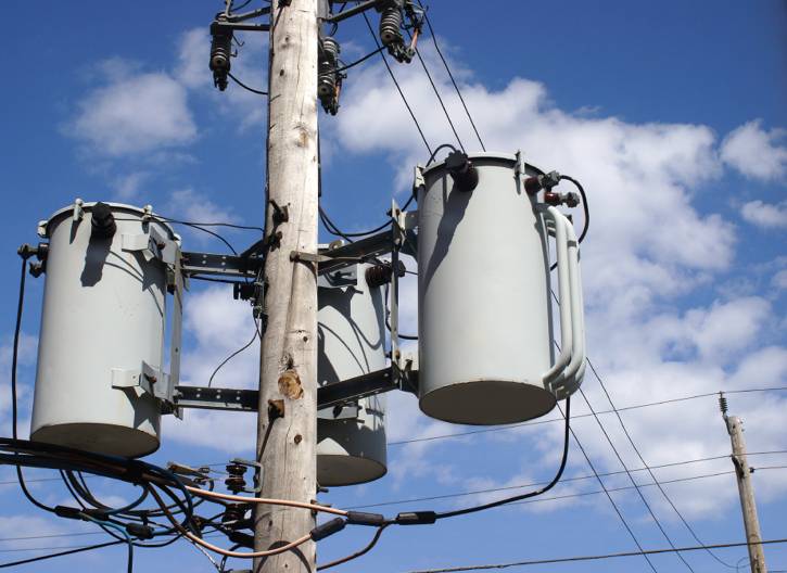
Figure 7 Three single-phase transformers wired as a three-phase transformer bank
Why use three single phase transformer banks in place of a single three-phase transformer? Two reasons: convenience and practicality.
The most common failure in any three-phase system is a grounding fault where one phase fails (shorts) to ground. When a single three-phase transformer is being used, the failure of one phase necessitates replacement of the entire transformer. However, when a bank of single-phase transformers is used, the failure of any phase requires the replacement of that phase transformer only; and it is easier and cheaper to replace a single phase transformer than a three-phase transformer.
Also, a group of three single phase transformers can be wired as any of the connections that were introduced in this section. Three phase transformers are manufactured in specific configurations, and therefore do not have this flexibility.
Open Phases in Three Phase Transformers
When one of the phase inductors in a wye-connected circuit opens, the entire circuit is effectively reduced to a single-phase circuit. This principle is illustrated in Figure 8a. When L1 opens, ΦA is isolated from the circuit. When this occurs, there is no current through L1 and only EBC is unchanged. In effect, the three-phase circuit has been reduced to a single phase circuit.
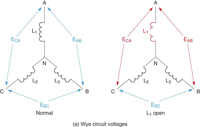
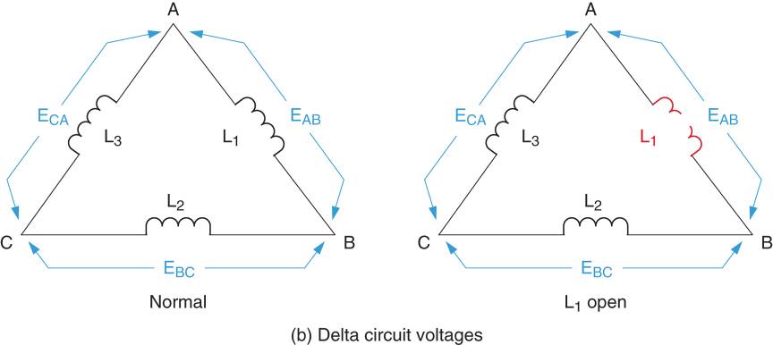
Figure 8 Wye (Y) and Delta( ∆) circuit voltages.
When one of the phase inductors in a delta connected circuit opens, the circuit still operates as a three-phase circuit (at reduced capacity). This principle is illustrated in Figure 8b. When L1 opens, none of the phase inputs is isolated from the circuit, so three-phase operation continues. However, there is no current through L1, which does affect the overall operation of the delta circuit. The kVA rating of the transformer is reduced because the power handling capacity of L1 is reduced to 0W. Even so, the circuit can continue three-phase operation at reduced opacity.
Open Delta Connection
As stated earlier, a delta connected transformer can operate at a reduced capacity if one of its phases opens. This principle makes it possible to produce a three-phase circuit using only two single-phase transformers. This Open Delta Connection, which is rarely encountered anymore, is shown in Figure 9.
Note that the kVA rating of an open delta connection is limited to approximately 87% of the sum of the nameplate kVA ratings of the two single-phase transformers. For example, if each transformer has a rating of 100kVA, then the kVA rating of the open delta bank is 200KVA × 87% = 174 kVA. This is due to the fact that only two transformers are carrying the load of three.
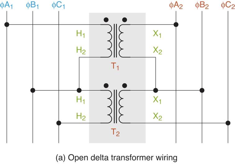
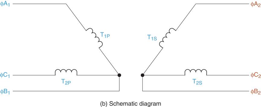
Figure 9 Open-delta transformer Schematic & Wiring Diagram
Three Phase Transformer Connections Key Takeaways
Understanding the operating characteristics of different three-phase transformer connections—such as delta-delta, wye-wye, delta-wye, and wye-delta—is crucial for selecting the right transformer configuration in various electrical applications. Each connection type offers unique advantages in terms of voltage levels, current flow, and the presence or absence of a neutral line, which directly affects their suitability for industrial, commercial, or transmission systems. Using banks of single-phase transformers adds flexibility and reliability, making maintenance easier and reducing downtime in case of faults. Moreover, knowledge of open-phase conditions and open delta connections is important for ensuring continued operation even when one transformer phase fails, albeit at reduced capacity.