This article mainly covers DC Motor Construction and its Parts with labelled diagrams. Furthermore, a cutaway view of the DC Motor is presented and discussed in detail.
The main parts of a typical DC motor are:
- field frame or yoke
- end-shields and bearings
- field poles
- field coils
- armature and commutator
- brush gear and brushes.
The major parts of a DC motor are shown in the exploded view in Figure 2.
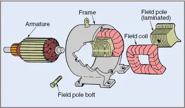
Figure 2 Major parts of a DC motor
DC Motor Construction
Field Frame or Yoke
In a DC motor, the field frame, or yoke, carries the field poles and also provides a magnetic path between poles. Since a material of high magnetic permeability is required, cast iron or steel is often used. The yoke has high mechanical strength and has the added advantage of retaining residual magnetism, a factor convenient for certain DC generator internal connections.
Modern practice is to roll the yoke from appropriate grades of sheet steel, weld the joint and machine it to size. Suitable feet or mounting brackets can then be attached, often with the addition of an eyebolt for ease of lifting and handling. The yoke is also machined, drilled and threaded for mounting the end frames or end-shields, terminal box and most other external parts.
End-Shields and Bearings
The purpose of end-shields is to support the bearings in which the armature rotates so the armature does not touch the field poles. Additionally, one of the end-shields usually has provision for mounting the brush gear for electrical connection to the rotating armature.
Designs of the end-shields and bearings vary according to the desired use of the machine. The end-shields might be waterproof for one situation or completely open for another. The bearings might be oiled bronze bushes, roller or ball bearings.
The end-shields and bearing can be seen in the dismantled view of a DC motor shown in Figure 3. The bearings are attached to the armature shaft.
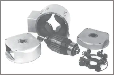
Figure 3 Dismantled DC motor cutaway view diagram
Field Poles
The field poles were once made of cast iron or steel. Modern DC motor poles are often fabricated from sheet-steel stampings riveted together, but the newest types of DC motor may have pressure-cast ferro ceramic poles for the highest efficiency currently available. Their high permeability provides a high concentration of magnetic flux at a particular position in the DC motor.
One field pole has been shown separated from its field coil in Figure 2. The outer surface of the poles is shaped to fit tightly against the inner surface of the field frame, while the inner surface of the pole is curved to closely follow the shape of the armature and the pole tips have been extended to contain the magnetic fringe.
This shaping permits a greater area in the flux path close to the armature and reduces the magnetic reluctance of the air gap. An incidental advantage is that the tips can be used to hold the field coils in position when the pole piece is bolted into place in the yoke.
Field Coils
Field coils are wound with insulated copper wire or bar according to their design purpose. If connected in series with the armature, they are called series coils and will be made of thick wire or even copper bar. If connected in parallel with the armature, they are called shunt coils and are usually wound with much thinner wire.
The actual construction of the coil will vary accordingly. Series coils must carry the high armature current, so they are wound with heavier conductors than shunt coils. Typical shunt and series field coils are shown in Figure 4(a) and (b) respectively.
The conductor sizes and comparative number of turns on the field coils can be shown in circuit diagrams as three turns for series coils and four or five turns for shunt coils.
Some fields are magnetically excited by a field coil consisting of two windings; one a series winding, the other a shunt winding. These are called compound (combined) windings (see Figure 4(c)).
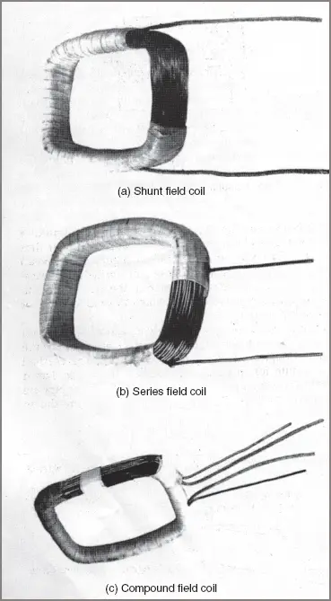
Figure 4 Field coil construction of DC Motor
In any case the magnetomotive force created must be great enough to produce the required magnetic flux through the yoke, field poles, air gaps and armature in a series-parallel magnetic circuit (see Figure 5).
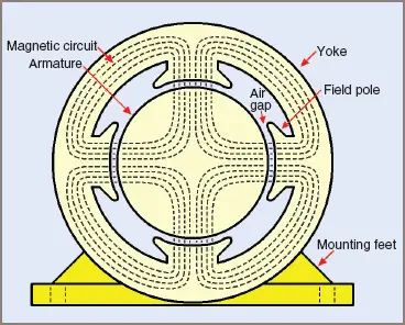
Figure 5 Magnetic circuit in a four-pole DC motor
Armature and Commutator
Armature
An armature core is assembled from a number of electrical steel laminations, usually keyed direct to the shaft. Figure 6(a) illustrates a typically shaped lamination.
Equally spaced slots are stamped around the circumference for the purpose of holding the armature conductors. Their shape influences the winding method used for any particular armature. Laminations for larger armatures also have punched ventilating holes. An unwound armature is shown in Figure 6(b).
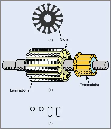
Figure 6 Typical lamination and armature before being wound in DC Motor
Coils that are wound and insulated before being placed in the slots can be used only in armatures with open-type slots. If semi- or fully-closed slots are used, it becomes necessary to wind in the coil one turn at a time. Some slot shape variations are shown in Figure 6(c). A typical armature from a small DC motor is shown in Figure 7.
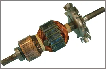
Figure 7 Armature for 0.25 kW 240 V DC motor
On large machines the central portion of the armature core is removed and the remaining laminated cylinder is attached to the armature shaft by means of radial arms (called a spider). This type of construction is shown in Figure 8.
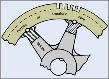
Figure 8 Larger size armature core construction in DC Motor
The advantage of this method of construction is a saving in the amount of material used and a consequent saving in weight. In addition, a flow of air through the holes left around the spider gives greatly increased cooling.
Commutator
The commutator is a most important part of the common DC machine. It consists of a set of copper or copper-alloy segments that are wedge-shaped in cross-section and insulated from one another, the armature shaft and the retaining rings by mica insulation (see Figure 9(a)).
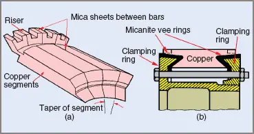
Figure 9 DC Motor Commutator construction
When assembled, the segments lie parallel to one another to form a cylinder. The ends of the segments are designed to accommodate specially formed micanite vee rings, which are used in conjunction with mild steel end rings to clamp the segments securely into position.
A sectional view of a commutator is illustrated in Figure 9(b). In very small commutators the fixing of segments is achieved by clamping under pressure and rolling over or crimping the edges of the clamping rings.
The clamping rings in an intermediate-sized commutator are designed to be screwed together, while in larger sizes the two clamping rings are pulled together by a circle of bolts. In all cases the inside of the steel rings helps locate the commutator on the armature shaft. The commutator may be pressed directly onto the shaft or bolted to the armature spider.
To make suitable provision for connection of coil leads to the commutator segments, slots are cut into the segment adjacent to the armature winding. This method is adequate for smaller commutators. For larger sizes a riser is fitted into the slot and the leads to the windings are connected to them or, in even larger DC motors, screws may be used to clamp the conductors to the commutator. Two types of connections are shown in Figure 10.
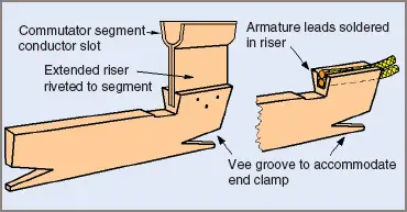
Figure 10 Commutator connections methods
Brush Gear and Brushes
Graphite or carbon brushes, sometimes mixed with copper dust, are used to provide a low resistance electrical connection between the armature windings and the external circuit. The brush makes a sliding contact with the commutator.
Figure 11 illustrates the brush gear for a four-pole machine. The carbon brushes must be able to move freely within the brush holder to ride up and down over any irregularities on the commutator surface, and to adjust for wear.
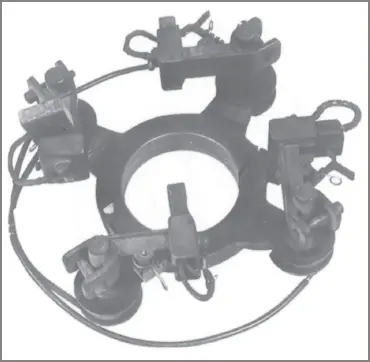
Figure 11 Brush gear assembly of a DC motor
The brush is usually connected to the brush holder with a flexible lead called a ‘pigtail’ and held down by a spring. The same connection terminal is used to connect to the external circuit.
The brushes must maintain contact with the commutator at a constant loading. By adjusting the spring tension, correct brush pressure can be obtained. Some brushes are tensioned by a spiral spring that provides a more constant pressure, thereby avoiding the need for adjustment.
The brush gear must be suitably insulated from the frame and in many cases the position of the brush around the commutator must also be adjustable. Figure 11 shows the brush mounting on an adjustable ring, which permits positioning of the brush gear. The reason for an adjustable position will be discussed in Section 6.2.
Action of the Commutator
As in the AC generator, with a DC generator an alternating voltage is also produced. However, instead of the ends of the loop being connected to slip-rings they are connected to a two-segment commutator, then through the brushes to the external circuit.
The brushes remain stationary, making contact with the segments of the commutator as they turn with the loop. The commutator acts as an automatic switch, reversing the current flow to the external circuit by exchanging the connections between the loop and the brushes.
Figure 12 shows a loop rotating in a magnetic field. Rotation of the loop through 360°E produces one cycle of alternating voltage which is switched twice to become two half waves of the same polarity. The output voltage is therefore mechanically rectified by the switching action of the commutator and a pulsating DC voltage appears across the load.
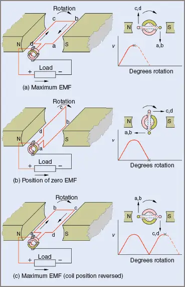
Figure 12 Rectifying action of a commutator in DC Motor
The output from such an elementary form of generator is not effective, being only 63 per cent efficient. Therefore practical machines must produce a more constant value of DC in order to get a more constant output. Practical armatures use a number of coils connected in series, evenly spaced around the armature.
The set of coils effectively forms one continuous coil evenly spread around the armature with many tapings where the DC current can be taken from the armature. If the number of coils could be infinite, the output would be a perfectly steady DC value.
With a practical generator, however, an alternating voltage is produced within each armature coil, and each individual coil would effectively be a different phase angle. For example, 24 coils would each be 15° apart electrically.
When the coil voltages are added as shown in Figure 13, the output voltage is the sum of the instantaneous voltage in each coil. Figure 13 shows the voltage resulting from 2, 4, 12 or 24 coils, demonstrating the increase in terminal voltage and frequency of the ripple voltage as well as the reduction in the size of the ripple voltage.
In fact, due to the inductive effect of the coils and the resistive switching resulting from the brushes straddling each pair of commutator segments as they pass underneath, the ripple voltage would be difficult to detect for 24 coils.
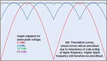
Figure 13 Resulting voltage from 2, 4, 12 or 24 coils