The article discusses the various types of DC motors—shunt, series, and compound—and explains their unique speed, torque, and torque-speed characteristics. It also covers how different field configurations affect performance, speed regulation, and stability under load conditions.
DC Motor Speed Characteristics
When a load torque is applied to a motor, the motor will slow down due to the load opposing the machine’s rotation. Eventually, the machine’s electromagnetic torque will equal the load torque and a new steady-state speed will be reached. How the speed changes depends on the type of field connections.
To quantify the variation of speed with load, we define the speed regulation:
\[\begin{matrix} SR=\frac{{{n}_{nl}}-{{n}_{fl}}}{{{n}_{nl}}} & {} & \left( a \right) \\\end{matrix}\]
Note that this is exactly the same format as the voltage regulation for the generator. Like the DC generator, the DC motor may have a shunt field, series field, or both. The shunt field may be separately excited or it may be excited from the same supply as the armature.
A compound machine (motor) may also be connected as a long shunt or short shunt, cumulative or differential. Differentially compounded DC motors are seldom used deliberately. We will now consider the speed characteristics of each type of DC motor.
Shunt Motor
The speed of the motor as a function of the armature current can be found by the following equation:
\[\begin{matrix} n=\frac{{{V}_{t}}-{{I}_{a}}{{R}_{a}}}{{{K}_{g}}{{\phi }_{p}}} & {} & \left( 1 \right) \\\end{matrix}\]
Appropriately enough, we call equation 1 the speed equation. For a shunt machine connected to a constant voltage, the flux per pole is constant.
Thus, the speed equation is a linear relation between n and Ia. Figure 1 shows the speed of a shunt DC motor as a function of armature current. The ideal case, described by the speed equation, is shown by the heavy solid line. As the load current becomes heavy, armature reaction tends to decrease the flux per pole, however.
If the denominator of the speed equation becomes smaller, then clearly the speed of the machine will be higher than otherwise expected. The dashed line in Figure 1 shows how moderate armature reaction might affect the speed of the motor.
Speed regulation is typically 8%-10% for the shunt DC motor. If the armature reaction is severe enough, the speed may start to actually increase with load, as shown by the dotted curve in Figure 1. This results in negative speed regulation, which is just as undesirable as negative voltage regulation is in a generator.
Many loads use more power at higher speeds, so we can get into an unstable condition with the motor increasing speed as the load gets larger and the load getting larger still as the speed increases. One solution is to add a series field, which will in crease the field as the load current increases.
Looking at equation 1, it should be evident that if the field of the DC motor is reduced to zero, the motor will speed up to unacceptably high speeds. Such a condition is called runaway and can result in severe damage to the motor.
If the field is lost, the armature accelerates to very high speed, causing large centripetal forces on the components of the armature, which can cause the commutator bars to be thrown off or the coils to move out of their slots. To avoid such damage it is important that the motor be protected against the loss of the field.

Figure 1: Speed characteristic of a shunt DC motor.
It is also instructive to consider the variation of the torque with the load current. Recall the electro magnetic torque equation (equation 2):
$\begin{matrix} {{T}_{d}}={{K}_{m}}{{\phi }_{p}}{{I}_{a}} & {} & \left( 2 \right) \\\end{matrix}$
If the flux is constant, we would obviously expect the torque to be a linear function of the armature current. Figure 2 shows torque as a function of armature current for a shunt DC motor. As was the case with the speed, however, the armature reaction has an effect. As the armature current increases, the flux per pole decreases, causing the electromagnetic torque to be somewhat lower than expected.
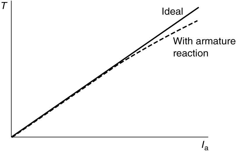
Figure 2: Torque characteristic of a shunt DC motor.
We can cross-plot speed versus torque by substituting from equation 2 for the current in the speed equation, which yields
\[\begin{matrix} n=\frac{{{V}_{t}}-{{R}_{a}}\left( \frac{{{T}_{d}}}{{{K}_{m}}{{\phi }_{p}}} \right)}{{{K}_{g}}{{\phi }_{p}}} & {} & \left( 3 \right) \\\end{matrix}\]
For a shunt motor with constant terminal voltage and no armature reaction, this is a linear relation between speed and torque, as shown by the solid line in Figure 3.
Armature reaction will cause the speed to fall off faster with torque and limits the torque of the machine at high current, as shown by the dashed line. This has the practical effect of limiting the starting torque of the shunt motor to about 125%-200% of rated torque and the starting current to the same percentage of rated current.

Figure 3: Torque-speed characteristic of a shunt DC motor.
Series Motor
The equivalent circuit for a series DC machine was shown in the following figure.
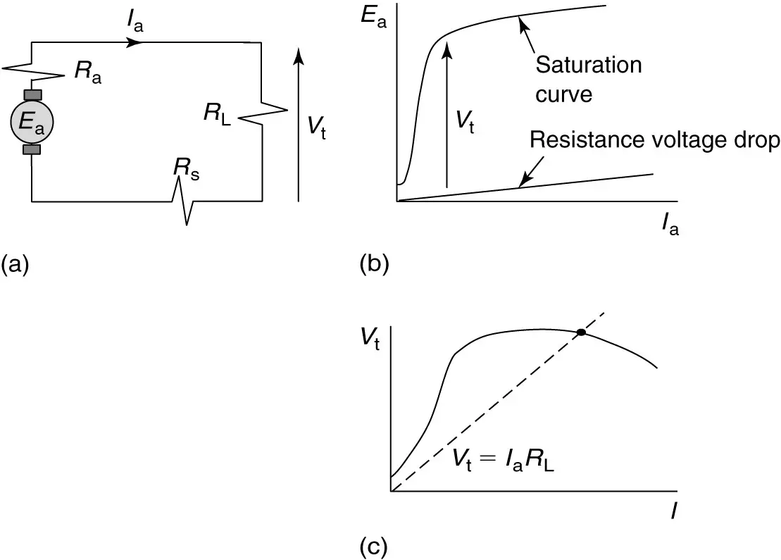
Figure: Series DC motor.
a. Equivalent circuit.
b. Saturation curve and voltage drop across armature and series field.
c. Terminal voltage.
The speed equation for the series DC motor is similar to the shunt, but we must include the series field resistance:
\[\begin{matrix} n=\frac{{{V}_{t}}-{{I}_{a}}\left( {{R}_{a}}+{{R}_{s}} \right)}{{{K}_{g}}{{\phi }_{p}}} & {} & \left( 4 \right) \\\end{matrix}\]
In the case of the series DC motor, however, the flux per pole is a function of the armature current.
In the linear portion of the magnetization curve, the flux is proportionate to the armature current, so we can replace the flux by a constant time the armature current. Splitting equation 4 into two terms and canceling the armature current from the numerator and denominator of the second term yields
\[\begin{matrix} n=\frac{{{V}_{t}}}{{{K}_{g}}K{{I}_{a}}}-\frac{\left( {{R}_{a}}+{{R}_{s}} \right)}{{{K}_{g}}K} & {} & \left( 5 \right) \\\end{matrix}\]
Equation 5 represents an inverse relationship between the speed, n, and the armature current, Ia , as shown in Figure 4. Thus, as the current goes to zero, the speed of the machine becomes very large. For this reason, it is essential to always keep a load on a series DC motor, which means the load should be connected directly to the shaft rather than via a belt or chain drive, which might become disconnected. As the current gets high, indicating a heavy load on the motor, the speed drops. Clearly, the speed regulation of the series motor is very poor.
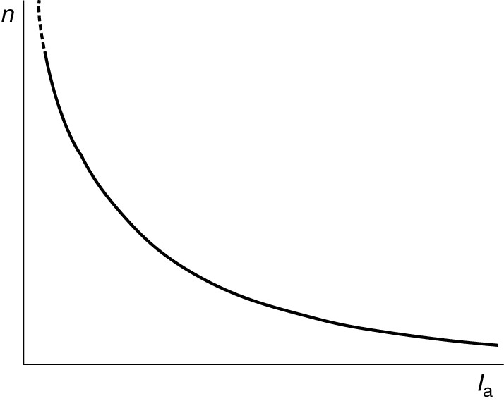
Figure 4: Speed characteristic of a series DC motor.
Again, if we are operating in the linear portion of the magnetization characteristic, then the flux is proportionate to the armature current and we can replace the flux by a constant times the current, yielding
$\begin{matrix} {{T}_{d}}={{K}_{m}}{{\phi }_{p}}{{I}_{a}}={{K}_{m}}K{{I}_{a}}{{I}_{a}}={{K}^{‘}}I_{a}^{2} & {} & \left( 6 \right) \\\end{matrix}$
From equation 6, we surmise that the torque of the series DC motor varies with the square of the armature current (in the linear portion of the magnetization curve). This is shown in Figure 5 by the solid line.
As the iron in the machine becomes saturated at high armature current (which is also the field current), the flux per pole essentially becomes constant. Thus, the curves in Figures 4 and 5 become linear at heavy values of armature current, as shown by the dashed line in Figure 5.

Figure 5: Torque characteristic of a series DC motor.
It is particularly interesting to plot speed vs. torque for the series motor. This is shown in Figure 4. The series DC motor produces very high starting torque and, as previously mentioned, will run away at no load.
As an example, series motors are useful for driving subway cars where high torque at standstill is required. 400% torque can be provided with only 200% current because of the squared relationship.
On the other hand, series motors would not be useful for electric cars because there would be little torque for passing at high speed on the highway.

Figure 4: Torque-speed characteristic of a series DC motor.
Compound DC Motors
Because compound motors have both series and shunt field windings, one might expect the characteristics of the compound motor to exhibit traits of both the series and shunt motor. This is true; however, the characteristics of compound motors vary greatly with the relative strength of the series and shunt fields. The more turns there are in the series field, the higher will be the starting torque, but the worse will be the speed regulation (20%-50%). Since there is a shunt field, the motor has a definite and safe no-load speed.
Many shunt DC motors have a small series coil with just a few turns (maybe only 1 or 2). This type of motor is called a stabilized shunt motor.
The series coil provides extra MMF at high armature cur rents, which offsets the armature reaction and prevents the machine from having negative speed regulation. In fact, the speed regulation of a stabilized shunt motor can be made to be very small, but positive.
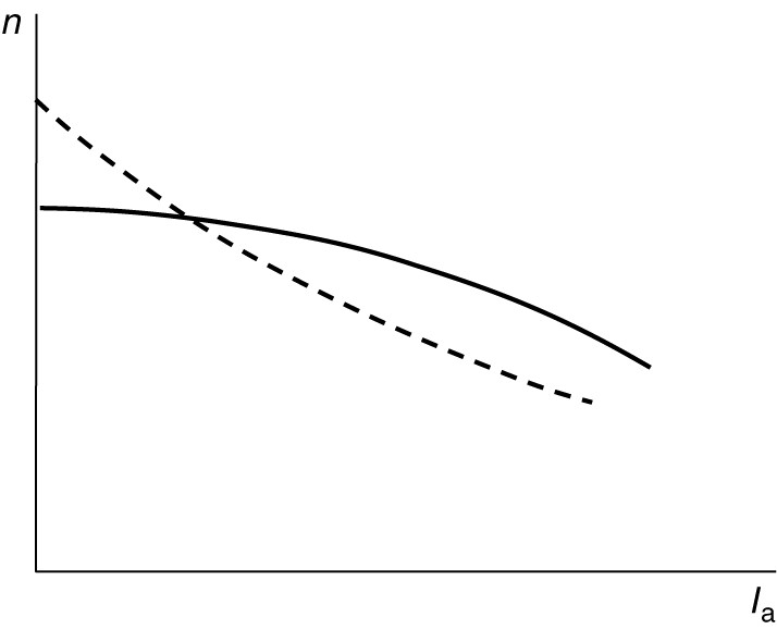
Figure 5: Speed characteristics of compound DC motors.
Figure 5 shows the speed vs. armature current characteristics of compound DC motors. The dashed curve has a heavy series field and exhibits poorer speed regulation while the solid curve has a weaker series field and acts more like a shunt motor.
Figure 6 shows the torque vs. armature current characteristics for series, shunt, and compound motors. As we have seen, the torque-current characteristic is linear for a shunt motor and parabolic for the series motor. As might be expected, the compound motor’s torque characteristic will lie somewhere between the series and shunt characteristics.
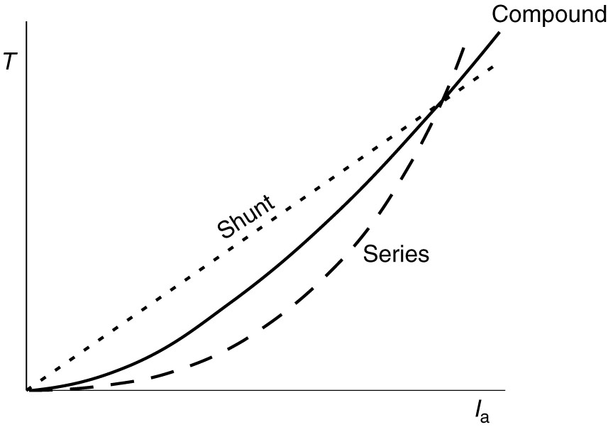
Figure 6: Comparison of torque characteristics for series, shunt, and compound DC motors.
Figure 7 shows the connections for cumulative compounding of both long- and short-shunt motors. Current is entering the motor and must enter both field windings at terminal 1 for the two field windings to produce flux in the same direction. Thus, the series winding has been reversed from what it was for generator operation.
Cumulative-compound machines will have positive speed regulation; i.e., the speed will drop as the load torque increases to its rated value.
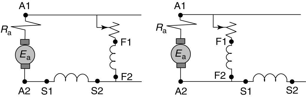
Figure 7: Compound motor connections.
Figure 8 shows the torque-speed characteristics of three compound machines. The solid curve droops slightly, corresponding to a light series winding, while the dashed curve droops much more, corresponding to a heavy series winding. The third curve, shown dotted, is one possibility which might arise in a differentially compounded motor.
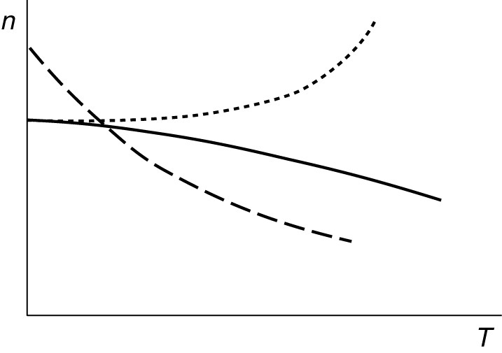
Figure 8: Possible torque-speed characteristics of compound motors.
Differentially Compounded DC Motors
This connection is almost never used deliberately, but occasionally motors are connected this way by accident.
Speed Regulation of Differentially Compounded DC Motor
However, the differential connection can provide excellent speed regulation, because applying load causes a drop in speed which means the C-EMF drops. When the C-EMF decreases, the armature current increases, causing the flux to drop due to the differential compounding, which causes a further decrease in the C-EMF. Thus, we can get large changes in armature current with little speed drop.
Starting Torque of Differentially Compounded DC Motor
The starting torque of a differentially compounded motor is poor because the series and shunt fields cancel each other. Thus it is usually necessary to short out the series field to start a differentially compounded motor.
If the series field is too strong, the motor speed becomes unstable as the load is added. Depending on the turns ratio of the two field windings, the motor may run away, as shown by the dotted curve in Figure 8, or it may stall or even cycle between forward and backward rotation. In any event, very high currents and torques are produced.
Types of DC Motors Key Takeaways
Understanding the speed and torque characteristics of different types of DC motors—shunt, series, and compound—is essential for selecting the appropriate motor for specific applications. Each motor type offers distinct advantages: shunt motors provide stable speed under varying loads, making them ideal for precision tools and conveyors; series motors deliver high starting torque, which is crucial for applications like cranes, electric trains, and elevators; and compound motors offer a balance between torque and speed regulation, making them suitable for heavy-duty machinery requiring both power and control. The correct application of these motor types enhances system efficiency, ensures operational safety, and optimizes performance across industrial, transportation, and automation systems.