In a three-phase service supplied by an electrical utility company, all three line voltages have the same magnitude and are displaced from one another by 120°. We can measure the magnitude of these voltages quite readily. However, the magnitudes do not tell us whether VBN leads VAN by 120° or lags behind it by 120°. The phase sequence (or phase rotation) of a three-phase system governs the direction of rotation of three-phase motors and the division of the current among the three lines feeding an unbalanced load.
Figure 1(a) shows that VBN lags behind VAN by 120° and VCN lags behind VBN by 120°. Therefore, the instantaneous voltage to line A passes through its positive peak value first, then the instantaneous voltage to line B passes through its positive peak value, followed by the instantaneous voltage to line C. Thus, this system has an ABC phase sequence.
If we reverse the leads to two of the generator coils, as in Figure 1(b), VBN now leads VAN by 120° and VCN leads VBN by 120°. Thus the phase sequence has been reversed and the system now has a CBA phase sequence.
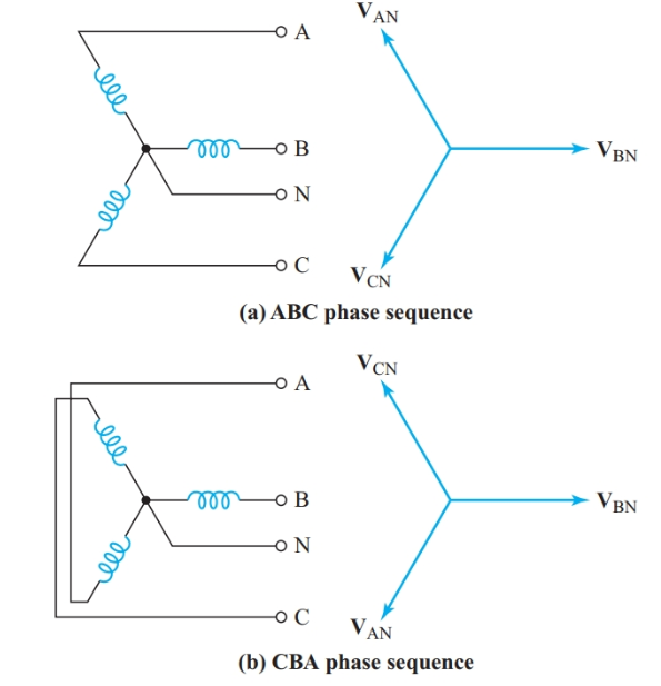
Figure 1 Phase sequence of a three-phase source
Once we have drawn a phasor diagram for the voltages in a 3φ system, we can easily read the phase sequence from the phasor diagram. Since the direction of rotation of a phasor is counterclockwise, the phase sequence is the order in which the voltage phasors would pass the reference axis if they rotate counterclockwise.
When we are given the line voltage and phase sequence of a three-phase source, as in Figure 2(a), we can draw a phasor diagram by placing one phasor (usually VBA) along the reference axis. As we read clockwise around the phasor diagram of Figure 2(b), all the first subscript letters of the voltage phasors must follow the specified phase sequence. The second subscript letters must also match the phase sequence.
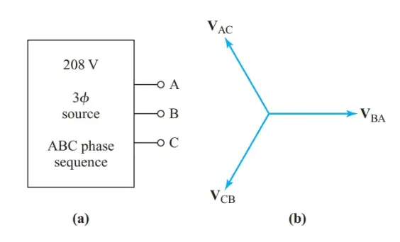
Figure 2 Determining phase sequence from a phasor diagram
The following example shows the effect of phase sequence on the line currents to an unbalanced load.
Example 1
${{Z}_{AB}}=52\angle -{{30}^{o}}\text{ , }{{Z}_{BC}}=52\angle +{{45}^{o}},\text{ and }{{Z}_{CA}}=104\angle {{0}^{o}}\text{ }$ are connected as a delta load to a 208-V 3φ source. Find the magnitude of the current in each line when the phase sequence of the source is ABC.
Solution
With ABC phase sequence,
$\begin{align}& {{I}_{AB}}=\frac{{{V}_{AB}}}{{{Z}_{AB}}}=\frac{208\angle {{0}^{o}}}{52\angle -{{30}^{o}}}=4\angle +{{30}^{o}}A \\& {{I}_{BC}}=\frac{{{V}_{BC}}}{{{Z}_{BC}}}=\frac{208\angle -{{120}^{o}}}{52\angle +{{45}^{o}}}=4\angle -{{165}^{o}}A \\& {{I}_{CA}}=\frac{{{V}_{CA}}}{{{Z}_{CA}}}=\frac{208\angle +{{120}^{o}}}{104\angle {{0}^{o}}}=2\angle +{{120}^{o}}A \\\end{align}$
Step 2
From the circuit diagram of Figure 3(a),
${{\text{I}}_{\text{A}}}\text{=}{{\text{I}}_{\text{AB}}}\text{-}{{\text{I}}_{\text{CA}}}=4\angle +{{30}^{o}}-2\angle +{{120}^{o}}=4.464+j0.268A$
Therefore,
${{\text{I}}_{\text{A}}}=4.5A$
${{\text{I}}_{\text{B}}}\text{=}{{\text{I}}_{\text{BC}}}\text{-}{{\text{I}}_{\text{AB}}}=4\angle -{{165}^{o}}-4\angle +{{30}^{o}}=-7.327-j3.035A$
Therefore,
${{\text{I}}_{\text{B}}}=7.9A$
${{\text{I}}_{\text{C}}}\text{=}{{\text{I}}_{\text{CA}}}\text{-}{{\text{I}}_{\text{BC}}}=2\angle +{{120}^{o}}-4\angle -{{165}^{o}}=2.863+j2.767A$
Therefore,
${{\text{I}}_{\text{C}}}=4.0A$
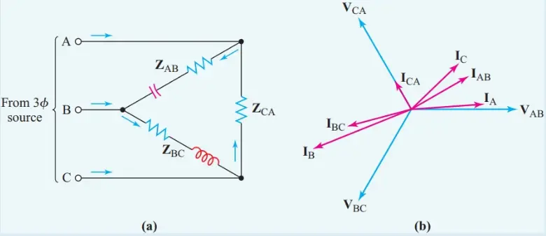
Figure 3 Phasor diagram for Example 1
You May Also Read: Zero Sequence Compensation in Three-Phase System