The article explains the advantages of polyphase system, focusing on two-phase alternators, constant power output, and the generation of rotating magnetic fields. It highlights how these features enhance efficiency and simplify the design of AC machines like motors.
The two-phase alternator in Figure 1(a) has two identical loops mounted on the same rotor. Since both loops have the same number of turns and rotate at the same angular velocity, the voltages induced in them have the same magnitude and frequency.
Loop A is mounted on the rotor 90° ahead (in the direction of rotation) of loop B. Consequently, the voltage in loop A always leads the voltage in loop B by 90°. A single-phase circuit has only one source of alternating current.
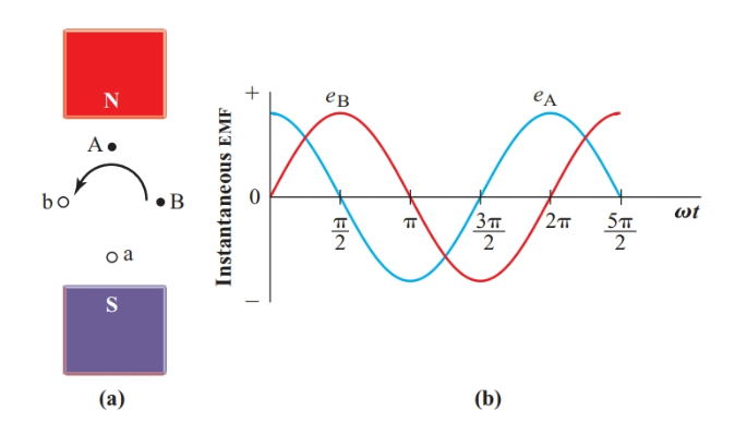
Figure 1 Simple two-phase alternator
In Figure 2, identical loads are connected to the two windings of the two-phase alternator. It is customary to represent each alternator winding with a coil rather than using a generator symbol. In Figure 2, the coils are at right angles to each other to indicate that their voltages are 90° out of phase.
Although each winding can be connected independently to its load as in Figure 2(a), two-phase circuits usually have a common or neutral lead as in Figure 2(b). This arrangement reduces the number of conductors needed from four to three.
The neutral current is the phasor sum of the two load currents. If the two loads are identical, the neutral current is only $\sqrt{2} $, or 1.414, times the current in each of the other conductors, as shown in the phasor diagram of Figure 3. With the two 120-V loads at 120 V, Line A and Line B each carry a current of 1 A and the neutral carries a current of 1.414 A. The total of these three currents is 3.414 A. The equivalent single-phase system supplying the two 120-V loads in parallel has two conductors that each carry 2 A, making a total of 4 A.
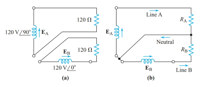
Figure 2 Simple two-phase system
A polyphase system needs less copper than a single-phase system to supply a given power at a given voltage.
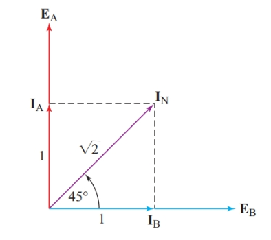
Figure 3 Phasor diagram for the neutral current in a simple two-phase system
Figure 4 shows the instantaneous power to the two identical loads in Figure 2. The total instantaneous power supplied by the alternator at any instant is the sum of the instantaneous power to the two loads. Since the two voltages are 90° out of phase, the instantaneous power to one load is greatest when the power to other load is zero.
If we check carefully, we find that the sum of the two instantaneous powers is the same at every instant. A constant power is an important advantage for large machines since it allows a steady conversion of mechanical energy into electric energy.
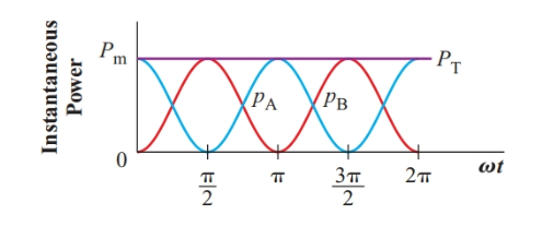
Figure 4 Instantaneous power in a balanced two-phase system
The total instantaneous power of a polyphase source is constant if the load on each phase of it is identical.
When the two-phase alternator is connected to a set of perpendicular coils as shown in Figure 5(a), each coil passes a sine wave of current, but the current in the B coils is 90° out of phase with the current in the A coils. The magnetic flux produced by the two currents at any instant depends on the magnitude of the two instantaneous currents.
At 0 rad, the current in the B coils is zero and the current in the A coils is at its maximum in the positive direction. The direction of the resulting magnetic field is indicated by the arrow in Figure 5(b).
At π/4 rad, the coils all pass a current of 0.707Im. Therefore, the total flux is the phasor sum of two perpendicular components with equal magnitudes. This total flux has the same density as at 0 rad, but its direction has changed as shown in Figure 5(c).
At π/2 rad, iA is zero and iB is at its positive maximum. The magnitude of the flux density is still the same, but the direction of the magnetic field, as shown in Figure 5(d), is now at right angles to its original direction at the start of the cycle.
Calculating the magnetic flux phasors through the rest of the cycle shows that the coil arrangement of Figure 5(a) produces a rotating magnetic field with a constant magnitude.

Figure 5 Producing a rotating magnetic field in a two-phase system
A polyphase source can develop a magnetic field that has a constant flux density and rotates at the frequency of the applied sine wave.
A compass needle placed in the center of the coils in Figure 5(a) will rotate with the magnetic field at a synchronous speed. Rotating magnetic fields greatly simplify AC motor construction.
A single-phase system produces a magnetic field that does not rotate. Instead, this magnetic field has a varying magnitude and reverses its direction each 180°.
Summary
• A two-phase alternator with two coils rotating 90° apart in a magnetic field produces two voltage sine waves, one of which leads the other by 90°.
• The instantaneous power output of a two-phase alternator with identical loads in each phase is constant.
• A set of perpendicular coils connected to a two-phase alternator produces a magnetic field with a constant flux density rotating at the frequency of the applied voltage.
Advantages of Polyphase System Key Takeaways
The features of polyphase systems—such as constant power output, reduced conductor requirements, and the ability to generate a rotating magnetic field—are highly valuable in practical applications. These advantages make polyphase systems ideal for powering industrial motors and generators, enabling smoother operation, greater efficiency, and more reliable energy conversion in large-scale electrical machinery.