Learn about the fundamental concepts of inductors and capacitors in electronics. Delve into the characteristics of ideal capacitors and inductors, including their equivalent capacitance and inductance, discrete variations, and the principles of energy storage within capacitors and inductors.
The ideal resistor was a useful approximation of many practical electrical devices. However, in addition to resistance, which always dissipates energy, an electric circuit may also exhibit capacitance and inductance, which act to store and release energy, in the same way that an expansion tank and flywheel, respectively, act in a mechanical system.
These two distinct energy storage mechanisms are represented in electric circuits by two ideal circuit elements: the ideal capacitor and the ideal inductor, which approximate the behavior of actual discrete capacitors and inductors. They also approximate the bulk properties of capacitance and inductance that are present in any physical system.
In practice, any element of an electric circuit will exhibit some resistance, some inductance, and some capacitance, that is, some ability to dissipate and store energy.
The energy of a capacitor is stored within the electric field between two conducting plates while the energy of an inductor is stored within the magnetic field of a conducting coil. Both elements can be charged (i.e., the stored energy is increased) or discharged (i.e., the stored energy is decreased).
Ideal capacitors and inductors can store energy indefinitely; however, in practice, discrete capacitors and inductors exhibit “leakage,” which typically results in a gradual reduction in the stored energy over time.
All the relationships for capacitors and inductors exhibit duality, which means that the capacitor relations are mirror images of the inductor relations. Examples of duality are apparent in Table 1.
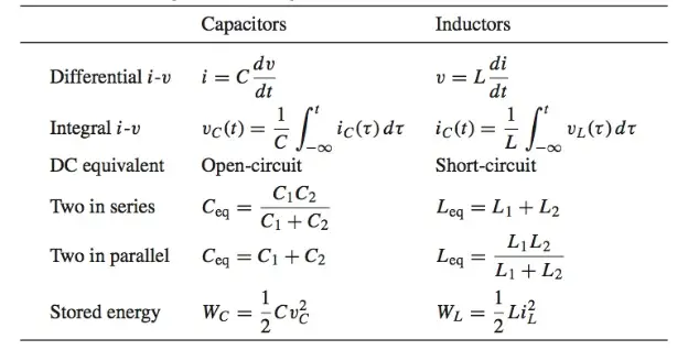
Table 1 Properties of capacitors and inductors
Ideal Capacitor
What is a Capacitor? A capacitor is a device that can store energy due to charge separation. In general, a capacitor (and thus, capacitance) is present when any two conducting surfaces are separated by a distance.
A simple example is two parallel plates of shared cross-sectional area A separated by a distance d. The gap between the plates may be a vacuum or filled with some dielectric material, such as air, mica, or Teflon. The impact of the dielectric material on the capacitance is represented by the dielectric constant k.
Figure 1 depicts a typical configuration and the circuit symbol for a capacitor.
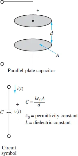
Figure 1 Structure of parallel-plate capacitor
The capacitance C of an ideal parallel-plate capacitor such as the one described above is:
\[\begin{matrix}C=\frac{k{{\varepsilon }_{o}}A}{d} & {} & \left( 1 \right) \\\end{matrix}\]
Where εo = 8.85 × 10⁻¹² F/m is the permittivity constant of a vacuum.
The presence of a dielectric or vacuum between the conducting plates does not permit charge to pass directly from one plate to the other. However, if the applied voltage across a capacitor changes, so will the accumulated charge. Thus, although no charge can literally pass from one plate of an ideal capacitor directly through to the other, a change in voltage will cause the accumulated charge to change, which is the equivalent effect of a current through the capacitor.
At all times, the charge separation is proportional to the applied voltage
$\begin{matrix}{{Q}_{C}}=C{{V}_{C}} & {} & \left( 2 \right) \\\end{matrix}$
where the parameter C is the capacitance and is a measure of the ability of the device to accumulate charge. The unit of capacitance is coulomb per volt, or farad (F). The farad is an impractically large unit for many common electronic applications; units of microfarads (1 μF = 10−6 F) and picofarads (1 pF = 10−12 F) are more common in practice.
The current through a capacitor is defined as the time rate of change of its stored charge. That is,
$\begin{matrix}{{i}_{c}}\left( t \right)=\frac{d{{q}_{c}}\left( t \right)}{dt} & {} & \left( 3 \right) \\\end{matrix}$
The i-v relationship for a capacitor is obtained from equation 3 by using equation 2 to plug in for qC (t). The result is:
$\begin{matrix}{{i}_{C}}\left( t \right)=C\frac{d{{v}_{C}}\left( t \right)}{dt} & {} & \left( 4 \right) \\\end{matrix}$
Equation 4 can be integrated to yield an equivalent i -v relationship for a capacitor:
$\begin{matrix}{{v}_{C}}\left( t \right)=\frac{1}{C}\int_{-\infty }^{t}{{{i}_{C}}\left( \tau \right)d\tau } & {} & \left( 5 \right) \\\end{matrix}$
One immediate implication of equation 4 is that the current through a capacitor in a DC circuit is zero. Why? Since the voltage across a capacitor in a DC circuit must, by definition, be constant, the time derivative of the voltage must be zero. Thus, equation 4 requires the current through the capacitor to also be zero.
A capacitor in a DC circuit is equivalent to an open-circuit.
Equation 5 indicates that the voltage across a capacitor depends on the history of the current through it. To calculate that voltage, it is necessary to know the initial voltage Vo (i.e., an initial condition) across the capacitor at some previous time to. Then:
$\begin{matrix}{{v}_{C}}\left( t \right)={{V}_{0}}+\frac{1}{C}\int_{{{t}_{o}}}^{t}{{{i}_{C}}\left( \tau \right)d\tau } & t\ge {{t}_{0}} & \left( 6 \right) \\\end{matrix}$
The significance of the initial voltage vC (to) = Vo is simply that, at time to, some charge was stored in the capacitor, resulting in Vo, according to the relationship Q = CV.
Equivalent Capacitance Formula
Just as resistors can be in series and parallel to yield an equivalent resistance, so capacitors can also be in series and parallel to yield an equivalent capacitance. The calculation rules are given below.
For two capacitors in series and parallel, the equivalent capacitances are, respectively:
$\begin{matrix}{{C}_{eq}}=\frac{{{C}_{1}}{{C}_{2}}}{{{C}_{1}}+{{C}_{2}}} & and & {{C}_{eq}}={{C}_{1}}+{{C}_{2}} & \left( 7 \right) \\\end{matrix}$
Notice that the rule for the equivalent capacitance of two capacitors in a series is the product divided by the sum, which is the same rule used for two resistors in parallel. Likewise, the equivalent capacitance of two capacitors in parallel is simply the sum of the two, which is the same rule used for two resistors in a series. The more general rules are illustrated in Figure 2.
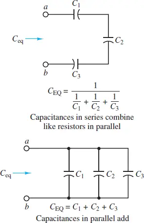
Figure 2 Equivalent capacitance in a circuit with series and parallel capacitors
When calculating equivalent capacitance, capacitors in series combine like resistors in parallel and capacitors in parallel combine like resistors in series.
Discrete Capacitors
Actual capacitors are rarely constructed of two parallel plates separated by air because this configuration either yields very low values of capacitance or requires very large plate areas.
To increase the capacitance (i.e., the ability to store energy), physical capacitors are often made of tightly rolled sheets of metal film, with a dielectric (e.g., paper or Mylar) sandwiched in between.
Table 2 illustrates typical values, materials, maximum voltage ratings, and useful frequency ranges for various types of capacitors. The voltage rating is important because any insulator will break down if a sufficiently high voltage is applied across it.
Table 2: Capacitors Materials and their Capacities
| Material | Capacitance range | Maximum voltage (V) | Frequency range (Hz) |
| Mica | 1 pF to 0.1 µF | 100–600 | 103−1010 |
| Ceramic | 10 pF to 1 µF | 50–1,000 | 103−1010 |
| Mylar | 0.001 µF to 10 µF | 50–500 | 102−108 |
| Paper | 1,000 pF to 50 µF | 100–10,000 | 102−108 |
| Electrolytic | 0.1 µF to 0.2 F | 3–600 | 10–104 |
In practice, actual capacitors exhibit some leakage between the plates. Imperfect construction techniques invariably provide some capability for the charge to pass from one plate to the other. This imperfection is often represented by an equivalent resistance in parallel with an ideal capacitor.
Energy Storage in Capacitors
The energy stored in a capacitor WC(t) may be derived easily from its definition as the time integral of power, which is the product of voltage and current:
$\begin{matrix}{{P}_{C}}\left( t \right)={{i}_{C}}\left( t \right){{v}_{C}}\left( t \right)=C\frac{d{{v}_{C}}\left( t \right)}{dt}{{v}_{C}}\left( t \right)=\frac{d}{dt}\left[ \frac{1}{2}Cv_{C}^{2}\left( t \right) \right] & {} & \left( 8 \right) \\\end{matrix}$
The total energy stored in the capacitor is found by integrating the power, as shown below:
\[\begin{matrix}{{W}_{C}}\left( t \right)=\int{{{P}_{C}}\left( \tau \right)}d\tau =\int{\frac{d}{d\tau }}\left[ \frac{1}{2}Cv_{C}^{2}\left( \tau \right) \right]d\tau & {} & \left( 9 \right) \\\end{matrix}\]
The final expression for the total energy stored in the capacitor can be written as:
${{W}_{C}}\left( t \right)=\frac{1}{2}Cv_{C}^{2}\left( t \right)$
Ideal Inductor
What is an Inductor? An inductor is an element that can store energy in a magnetic field within and around a conducting coil. In general, an inductor (and thus, inductance) is present whenever a conducting wire is turned to form a loop.
A simple example is a solenoid, which is a narrow and tightly wound coil of length l, cross-sectional area A, and N turns. Inductors are typically made by winding wire around a core, which can be an insulator or a ferromagnetic material, as shown in Figure 3. A current through the coil establishes a magnetic field through and around the core. In an ideal inductor, the resistance of the wire is zero.
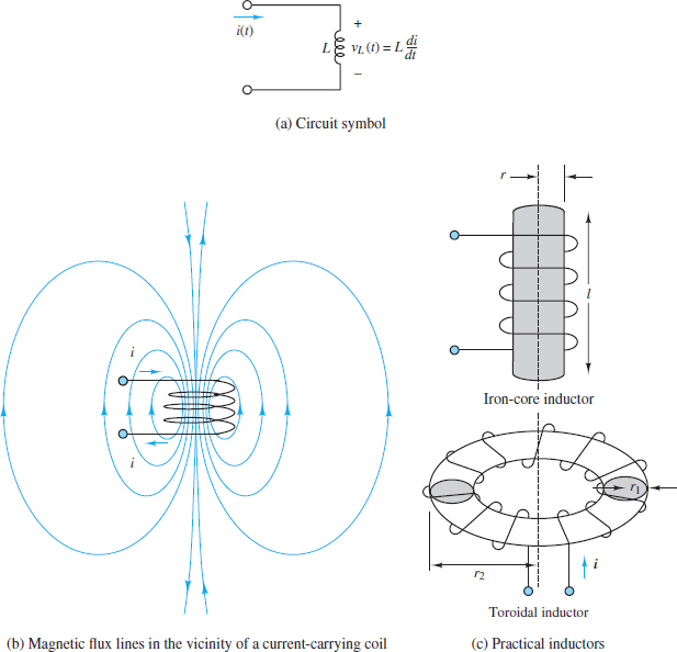
Figure 3 Inductance and practical inductors
The inductance L is defined by the following ratio:
\[L\equiv \frac{N\Phi }{{{i}_{L}}}\]
Where $\Phi $is the magnetic flux through the inductor core and iL is the current through the inductor coil.
The inductance of an ideal solenoid is:
\[L=\frac{\mu {{N}^{2}}A}{\ell }\]
where μ is the permeability of the core. Another inductor found in many applications is the toroid, which is also depicted in Figure 3. Expressions for the inductance of toroids with rectangular and circular cross-sections are readily found.
The inductance of a coil is measured in henrys (H) where
$\begin{matrix}1H={}^{1V-s}/{}_{A} & {} & \left( 10 \right) \\\end{matrix}$
Henrys are reasonable units for practical inductors, although millihenrys (mH) are very common, and microhenrys (μH) are occasionally found.
The i-v relationship for an inductor is derived directly from Faraday’s law of induction but with the total flux $N\Phi $ replaced by Li from the definition of inductance L. The result is:
$\begin{matrix}{{v}_{L}}\left( t \right)=L\frac{d{{i}_{L}}\left( t \right)}{dt} & {} & \left( 11 \right) \\\end{matrix}$
Equation 11 can be integrated to yield an equivalent i -v relationship for an inductor:
$\begin{matrix}{{i}_{L}}\left( t \right)=\frac{1}{L}\int_{-\infty }^{t}{{{V}_{L}}\left( \tau \right)d\tau } & {} & \left( 12 \right) \\\end{matrix}$
One immediate implication of equation 11 is that the voltage across an inductor in a DC circuit is zero. Why? Since the current through an inductor in a DC circuit must, by definition, be constant, the time derivative of the current must be zero. Thus, equation 11 requires the voltage across an inductor to also be zero.
An inductor in a DC circuit is equivalent to a short-circuit.
Equation 12 indicates that the current through an inductor depends on the history of the voltage across it. To calculate the current, it is necessary to know the initial current I0 (i.e., an initial condition) through the inductor at some previous time t0. Then:
$\begin{matrix}{{i}_{L}}\left( t \right)={{I}_{0}}+\frac{1}{L}\int_{{{t}_{o}}}^{t}{{{V}_{L}}\left( \tau \right)d\tau } & t\ge {{t}_{0}} & \left( 13 \right) \\\end{matrix}$
Equivalent Inductance Formula
Just as resistors can be in series and parallel to yield an equivalent resistance, so inductors can also be in series and parallel to yield an equivalent inductance. The calculation rules are given below.
For two inductors in series and parallel, the equivalent inductances are, respectively,
\[\begin{matrix}{{L}_{eq}}={{L}_{1}}+{{L}_{2}} & and & {{L}_{eq}}=\frac{{{L}_{1}}{{L}_{2}}}{{{L}_{1}}+{{L}_{2}}} & \left( 14 \right) \\\end{matrix}\]
Notice that the equivalent inductance of two inductors in a series is simply the sum of the two, which is the same rule used for two resistors in a series. Likewise, the rule for the equivalent inductance of two inductors in parallel is the product divided by the sum, which is the same rule used for two resistors in parallel. The more general rules are illustrated in Figure 4.
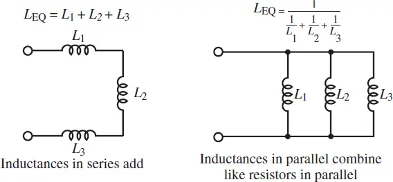
Figure 4 Equivalent inductance in a circuit with series and parallel inductors
When calculating equivalent inductance, inductors in series combine like resistors in series and inductors in parallel combine like resistors in parallel.
Duality
All the relationships for capacitors and inductors exhibit duality, which means that the capacitor relations are mirror images of the inductor relations. Specifically, the roles played by voltage and current in a capacitor relation are reversed in the analogous inductor relation. For example, the i-v relationships for capacitors and inductors, respectively, are:
\[\begin{matrix}i=C\frac{dv}{dt} & and & v=L\frac{di}{dt} \\\end{matrix}\]
Notice that the inductor relation is obtained from the capacitor relation by replacing i with v and v with i. It is also necessary, of course, to replace the capacitance C with the inductance L. Another example of duality is found in the energy storage relations for capacitors and inductors.
Duality is also at work in other relations not involving voltage and current explicitly. For example, consider the rules for calculating equivalent capacitance and equivalent inductance. Capacitors in series combine like inductors in parallel, while capacitors in parallel combine like inductors in series.
Another example of duality is seen in the DC behavior of capacitors and inductors. In a DC circuit, a capacitor acts like an open circuit, while an inductor acts like a short-circuit
Energy Storage in Inductors
The energy stored in an inductor WL(t) may be derived easily from its definition as the time integral of power, which is the product of voltage and current:
$\begin{matrix}{{P}_{L}}\left( t \right)={{i}_{L}}\left( t \right){{V}_{L}}\left( t \right)={{i}_{L}}\frac{d{{i}_{L}}\left( t \right)}{dt}=\frac{d}{dt}\left[ \frac{1}{2}Li_{L}^{2}\left( t \right) \right] & {} & \left( 15 \right) \\\end{matrix}$
$\begin{matrix}{{W}_{L}}\left( t \right)=\int{{{P}_{L}}\left( \tau \right)}d\tau =\int{\frac{d}{d\tau }}\left[ \frac{1}{2}Li_{L}^{2}\left( \tau \right) \right]d\tau & {} & \left( 16 \right) \\\end{matrix}$
The final expression for the total energy stored in the inductor can be written as:
${{W}_{L}}\left( t \right)=\frac{1}{2}Li_{L}^{2}\left( t \right)$
Note, once again, the duality with the expression for the energy stored in a capacitor, in equation 9.