The article provides an overview of various methods used to measure power in three-phase circuits, specifically focusing on the one-wattmeter, two-wattmeter, and three-wattmeter techniques. It also discusses practical considerations for meter selection based on circuit configuration, load balance, and measurement accuracy requirements.
Different methods are utilized in order to measure three-phase power in a three-phase circuit. In this particular article, we are going to discuss the following methods in detail:
One Wattmeter Method
Two Wattmeters Method
Three Wattmeters Method
A customer of a three-phase electrical service, three-wire or four-wire, will have a permanently installed meter that measures at least energy (watt-hour) consumption. The meter will be owned by the utility and provided for billing purposes.
Depending on the area and the utility’s policies, the meter may also measure other parameters for billing purposes. Larger users of electrical power are also often billed for reactive power factor and “demand.”
Temporary measurements of a three-phase three-wire circuit may be conducted for any one of several possible reasons by any one of several methods. The preferred method is by means of a three-phase power meter, a power analyzer, or a power quality meter.
Although more cumbersome, three-phase power may also be measured with a single-phase power meter or, depending on the application, several single-phase power meters. This option might be selected if, for example, a three-phase meter is not conveniently available.
The selection of meters and the method chosen might depend on a variety of conditions, including
- Types and number of meters on hand
- Balanced or unbalanced load
- The rate of change of load
- The frequency at which readings are to be made
- Required accuracy
If only one single-phase wattmeter is on hand, there is only an occasional need for wattage measurements, and the loads change slowly; one single- phase wattmeter can usually provide adequate results. At the other end of the spectrum where there is a frequent need for measurements and the loads change rapidly, a three-phase meter, a power quality meter, or a power analyzer would be a better choice.
If one understands how single-phase meters can be used to measure power, it then becomes much easier to understand how a three-phase power meter functions. Power can also be determined by any means that permits measuring current, voltage, and current lead/lag.
One Wattmeter Method to Measure Power in a Three-Phase, Three-Wire Circuit
A possible procedure to measure the total circuit power of a balanced three-phase three-wire circuit would use the measurement of the power of only one phase. Since by definition all three phases have equal power consumption, the total power consumption is triple the power measurement of any one phase.
This procedure would, of course, require access to the conductors that carry the phase currents as well as the conductors that deliver voltage potentials to the phases.
A procedure for measuring the phase power of a balanced delta circuit is shown in Figure 1. The phase potentials of a delta circuit are usually accessible, but the conductors carrying the phase currents may not be conveniently accessible. Usually, a different method would be preferred.
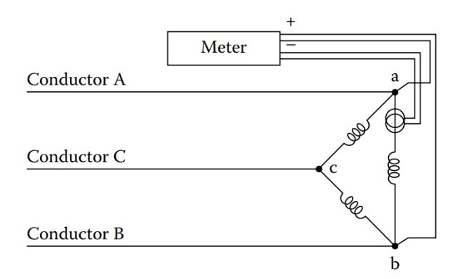
Figure 1: Measuring Power of a Delta Circuit.
A procedure for measuring the power of one phase of a balanced wye circuit is shown in Figure 2. However, in many instances, the measurements depicted in Figure 2 may not be physically practical.
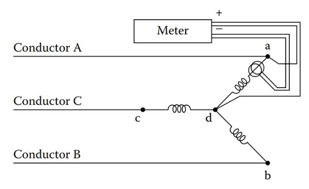
Figure 2: Measuring Power of a WYE Circuit.
Generally, the current of a wye circuit may be measured since the phase current is the same as the line current. However, access to the point where the phases tie together (point “d” in Figure 2) may not be readily accessible for a measurement. This would be the case, for example, if the circuit is a wye wound motor.
Generally, a connection of a potential lead to point “d” would not be required for a balanced circuit. This would be true of a wye wound motor since the currents of the three phases would be equal or nearly equal. Accordingly, the voltage can be calculated by the known relationship
\[{{V}_{P}}=\frac{{{V}_{L}}}{\sqrt{3}}\]
Under some circumstances, a single portable (single-phase) wattmeter can be used to obtain adequate readings in an unbalanced three-phase three- wire circuit. As mentioned earlier, this arrangement would be practical only if the measured parameters remain constant throughout the period of time during which the measurements are made.
The arrangement of Figure 3 shows a typical configuration that could be used to determine total circuit power with a single meter. To obtain a reading, the meter is first connected as shown in position #1. The current in conductor A is measured as well as voltage C–A. A reading is taken, and the meter is then moved to position #2. In position #2, the current in conductor C is measured as well as voltage C–B. The two readings are added to determine total circuit power. Alternate positions for measuring total power would involve the use of different conductors as explained later.
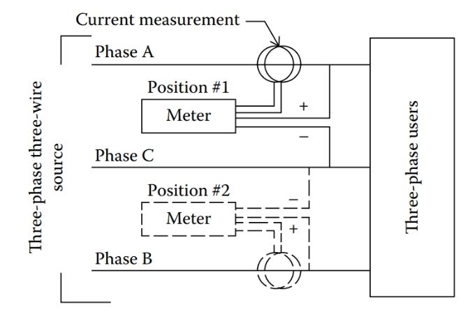
Figure 3: Use of a Single Wattmeter.
Two Wattmeters Method to Measure Power in a Three-Phase, Three-Wire Circuit
An effective and practical means of measuring power in unbalanced three-phase three-wire circuits involves the use of only two wattmeters in what is commonly called the “two-wattmeter method.”
Total power is determined at any selected instant by the sum of the readings indicated on the two watt- meters. The wattmeters determine power by measuring line parameters, that is, line potentials and currents. The two wattmeters are to be located in the three-phase lines that lead to the load as depicted in Figure 4.
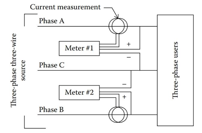
Figure 4: Use of Two Wattmeters.
Only two currents are measured, and the voltages are measured as shown in the figure. In Figure 4, the two wattmeters are designated as meter #1 and meter #2.
In one possible configuration, meter #1 measures the current in conductor A as well as voltage C–A. The positive voltage lead of meter #1 is connected to phase A, and the negative voltage lead is connected to phase C.
Meter #2 measures current in conductor B as well as voltage C–B. The positive voltage lead is connected to phase B, and the negative lead is connected to phase C.
An alternate 2 m configuration is shown in Figure 5, where the current coils are shown in phases A and C. In fact, the current measurements can be in any two of the three phases: A–B, A–C, or B–C. The positive potential leads are in contact with the respective phase conductor and the negative leads joined together and in contact with any voltage.

Figure 5: Alternate Use of Two Wattmeters
While an acceptable method of measuring total power of a three-phase circuit, the two wattmeter method has certain limitation.
If the (line) current measured by meter #1 (of Figure 4 or 5) leads the reference potential of the meter by less than 90°, meter #1 will correctly indicate the value of measured power. (A line current that leads potential by 90° would correspond to a power factor in a balanced circuit of 0.50.)
However, when line current leads the measured potential by more than 90°, problems may ensue depending on the type of meter used. If the wattmeter is of the electromechanical type, that is, one that uses internal coils to determine power, beyond 90°, there would be no indication of power level. In this case, a reading may be obtained by reversing potential leads and subtracting the reading of meter #1 from the reading of meter #2 since the reading of meter #1 would be a negative value. Some digital-type wattmeters would indicate a negative reading in which case there would be no need to reverse leads.
With the two wattmeter method of measuring circuit power, it is possible to have some 20 or more possible incorrect connections. Yet, there is only one set of connections that will provide correct readings. For this reason, correct positioning of all CT connections and potential connections are needed to ensure valid readings.
Three Wattmeters Method to Measure Power in a Three-Phase, Three-Wire Circuit
It is possible, and at times desirable, to measure all three line currents of a three-phase three-wire circuit along with the three sets of line potentials. This might be the case, for example, if the three line currents are to be monitored in addition to total circuit power.
In the case of an unbalanced delta circuit, total power consumption can be determined by measuring the power of each phase. This could be done, typically, with the configuration represented in Figure 6.
The total power consumption of the circuit would be the sum of the readings of the three wattmeters. As indicated in Figure 6, the current transformers are located in each of the three phases.
However, in many instances, the arrangement of Figure 6 is not practical since it is often not convenient to read the currents of the phases of a delta circuit.
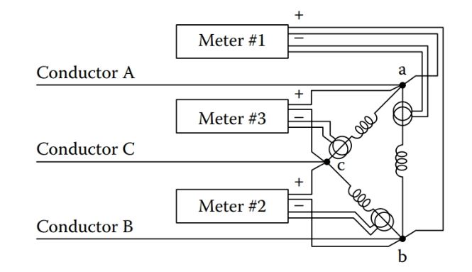
Figure 6: Measuring Power of a Delta Circuit.
In the case of a three-phase three-wire wye circuit, three single-phase wattmeters could be used in some cases to measure total power in the configuration of Figure 7.
The total circuit power is the sum of the phase powers. If the circuit is, say, configured in a wye configuration, as would be the case with a wye wound motor, it would generally not be possible to access the “d” point represented in Figure 7.
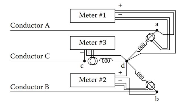
Figure 7: Measuring Power of a WYE Circuit.
An alternate method of measuring circuit power involves the use of three separate single-phase wattmeters to measure line parameters as represented in Figure 8. The users could be delta, wye, or any mix thereof. The positive potential leads of each of the meters is in contact with the respective phase in which the CT is located. The negative leads of the instruments are joined together. The negative leads can be connected to ground although a connection to ground is not necessary.
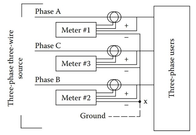
Figure 8: Three-Phase Three-Wire Measurement.
At first, it may seem strange to a reader that with the use of three wattmeters as depicted in Figure 8, all three negative leads of the instruments are joined together. In fact, this is the correct procedure. Regardless of the voltage (to ground) of the negative leads, the sum of the measurements of the wattmeters is the total circuit power.
In addition, if the three-phase three- wire circuit is derived from a three-phase four-wire circuit, and the negative leads of the three wattmeters are connected to ground potential, the measurements of each wattmeter will indicate the respective power delivered by that phase, that is, phase A, phase B, and phase C.
The configuration represented in Figure 8 is an effective method of measuring the total power of a three-phase three-wire circuit.
If only total circuit power is needed, the use of three wattmeters as depicted in Figure 8 offers no advantage over the two-wattmeter method. In fact, the three-wattmeter method requires three current measurements instead of the two of the two-wattmeter method.
On the other hand, the use of three CTs allows monitoring of the line currents as well. The use of a single three-phase wattmeter, rather than the use of three single-phase watt-meters, would generally be a more practical means to measure circuit power of a three-phase three-wire circuit.
Although the power of a balanced three-phase three-wire circuit can be measured with a single current measurement, unbalanced circuits require a minimum of two current measurements to establish a value of total circuit power.
If each of the three phases is to be monitored for currents as well as power, then three current measurements are required. For this reason, watt-meters are available for use with one, two, or three CTs. A possible configuration using a single instrument is depicted in Figure 9.
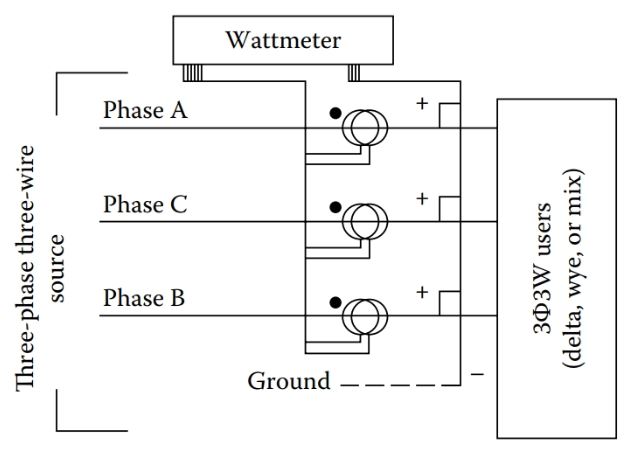
Figure 9: Three Phase-Three Wire Wattmeter.
Three Phase Power Measurement in Three Phase Circuits Key Takeaways
The accurate measurement of power in three-phase circuits is essential for system monitoring, efficiency analysis, load balancing, and effective billing. Each of the discussed methods—the one-wattmeter, two-wattmeter, and three-wattmeter techniques—offers specific advantages depending on circuit configuration, load conditions, and the level of accuracy required. For example, the one-wattmeter method is suitable for balanced loads, while the two-wattmeter method provides reliable results in both balanced and unbalanced three-wire systems. The three-wattmeter method, though more complex, allows for precise individual phase monitoring, which is valuable in detailed system diagnostics. These methods are not only foundational for utility billing and industrial energy management but also play a critical role in ensuring electrical safety, system optimization, and compliance with power quality standards.