When bringing a synchronous generator online, we are faced with the necessity of paralleling it with the rest of the power system. Figure 1 illustrates the problem.
Conditions for Synchronizing the Generator with the Grid (Power System)
Once the generator is operating, we would like to close the switch to connect it to the power system. The question, then, is what conditions should be present before the switch can be closed?
With a little bit of reflection, one might come up with the following four factors:
- The magnitudes of the generator and bus voltages should be the same.
- The frequency of the generator and bus voltages should be the same.
- The phase sequence of the three phases of the generator and the bus should be the same.
- The voltages of the generator and bus should be in phase.
Obviously, if any of these four factors is not true, there could be a voltage across the open switch terminals. Closing the switch would insert essentially zero impedance in the circuit, resulting in extremely high currents.
The phase sequence is particularly important. If the generator is producing an ABC sequence and the bus is operating with a CBA sequence, then closing the switch creates a rotating magnetic field that opposes the rotation of the machine. With the rotor spinning in the opposite direction of the stator magnetic field, extremely high pulsating torques are created, and there have been cases where the shaft of a machine was actually fractured due to these high braking torques.
Clearly, we would like to have an indication that there are no voltages across the poles of the three-phase switch in Figure 1 before we close the switch.
Fortunately, there are several manual techniques that have been used for many years as well as modem automatic electronic devices that allow safe paralleling of synchronous generators.

FIGURE 1: The problem of synchronizing a generator with the power system.
Three-Bulb Method
In the three-bulb method, a light bulb is placed across each pole of the three-phase switch that connects the generator to the power system, as shown in Figure 2(a).
The objective is to close the switch when all of the lights are dark, as that would indicate that each pole of the switch has nearly zero voltage across it.
Consider each of the four criteria we have listed. If the generator and the bus are operating at significantly different voltage levels or if they are separated by a constant phase angle, then all three poles of the switch will have voltages across them and all three bulbs will be on all of the time.
If the generator and the bus have different frequencies, then the phasor voltages will rotate at different speeds. Figure 2 (b) shows the two sets of phasor voltages. At some point, the two sets will come into phase with each other and the bulbs will go dark, but then they will drift out of phase due to the different rotating speeds. Thus, if the bus and generator have the same phase sequence, as shown, the bulbs will go light and dark together.
On the other hand, if the phase sequences are different, as shown in Figure 2(c), then only one of the phases can be in phase at any one time. Thus, the lights would go dark sequentially, one at a time. Note that the bulbs will be dark for a period of time when the voltage is too low to light them but not zero.
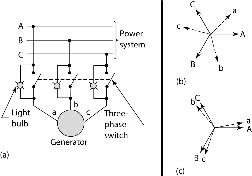
FIGURE 2: Three-bulb method for synchronizing a generator to an infinite bus.
- Schematic.
- Phasor diagrams of generator and bus voltages with the same phase sequences.
- Phasor diagrams of generator and bus voltages with opposite phase sequences.
To properly parallel a generator using the three-bulb method, the generator should be brought up to a few RPM over synchronous speed and the excitation should be adjusted so that the voltages on the two sides of the switch are approximately equal.
If the phase sequences are correct, then the bulbs should be glowing and be darkening together. With the generator running only a few RPM above synchronous speed, the cycle time for the bulbs to lighten and darken should be five to ten seconds. If that is the case, then the switch can be closed during the middle of the dark cycle and the generator will pull into synchronism with the infinite bus.
If the phase sequence is incorrect, then the bulbs will go dark one at a time. In that case, the generator should be shut down and two of its connections to the switch should be reversed. Then the process can be repeated.
“Note that it is important that the generator is operating slightly above synchronous speed. That way, when the switch is closed, the generator must slow down slightly, which means it will deliver power to the bus. If the machine was running below synchronous speed, it would have to speed up when the switch was closed, which would require that it draws power from the bus, making it a motor.”
The light bulbs must have a voltage rating of twice the phase voltage since the voltages can be 180° out of phase. Obviously, on higher voltage systems, that can be a problem. To solve that, transformers can be used.
The Three-Bulb Method with Transformers
Transformers can be used to reduce the voltage seen by the bulbs, as shown in Figure 3(a). The operation of the system is identical to the three-bulb method. Here two open-delta transformers are used.
One open-delta bank has the high side connected between the lines of the bus, and the other has the high side connected to the generator output. The low sides of the two banks are connected to the light bulbs, as shown.
One problem with the three-bulb method is that it does not give an indication of which side has the higher frequency. By changing the connections, it is possible to get that information.
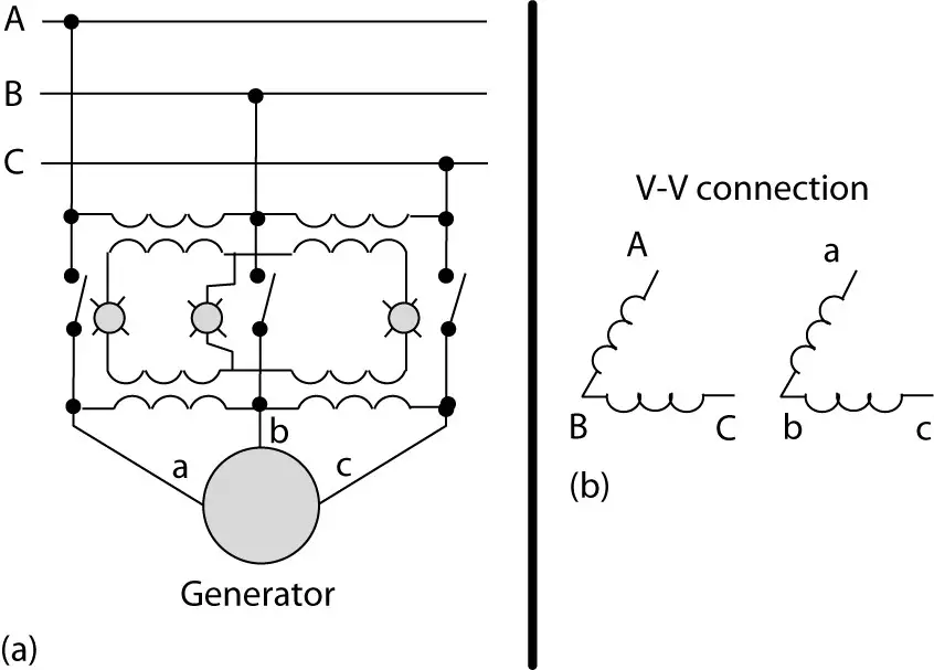
FIGURE 3: Three-bulb method using transformers.
- Schematic.
- Open-delta connection.
Two-Light-and-One-Dark-Method
A variation of the three-bulb method that provides frequency information is shown in Figure 4.
Here, the two outside phases are cross-connected. When the system and the generator are properly phased, the middle bulb is dark and the outside ones are bright. If the frequencies are different, the bulbs will flash sequentially, and the direction of the flashing tells whether the generator speed is high or low.
This technique also offers the advantage of being able to close the switch when the two outside bulbs are at their maximum (at equal brightness). Since it is easier to determine the maximum brightness than the middle of the dark period, this allows the operator to close the switch when the system and generator are more nearly in phase. Another way to determine the relative frequency or phase angle is with a synchroscope.
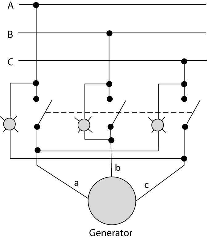
FIGURE 4: Two-bright-and-one-dark method of synchronization.
Synchroscope
The synchroscope is a device that indicates the instantaneous angle between two voltages of the same frequency or that shows the frequency difference between them if they are not the same.
Figure 5 is a drawing of a phase angle meter/synchroscope. Obviously, if the frequencies are different, the angle between the voltages is constantly changing, which means the pointer will rotate.
The generator would be connected to the left terminals and the bus to the right (transformers may be required to step the voltages down). If the generator’s frequency is too high, the needle will rotate clockwise; if it is too low, the needle rotates counterclockwise.
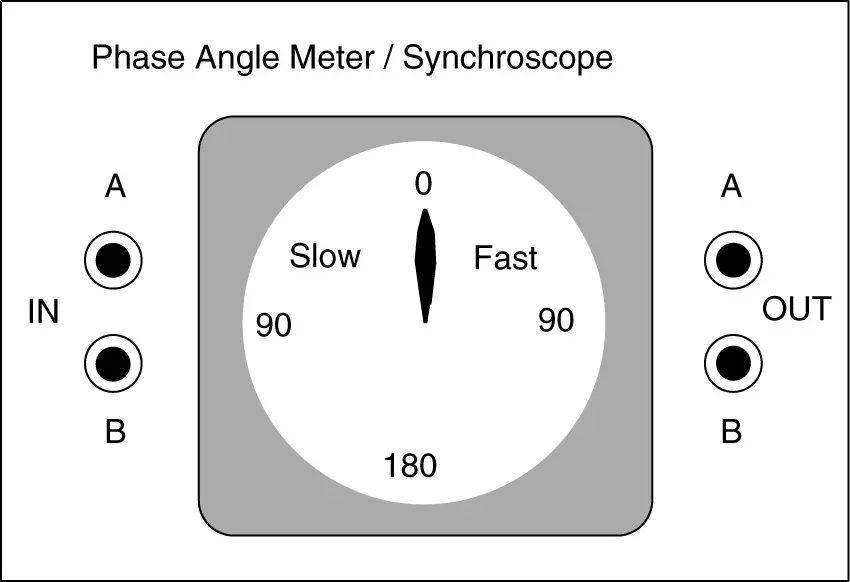
FIGURE 5: Illustration of a phase angle meter/synchroscope.