The article provides an overview of apparent, active and reactive power in AC circuits, explaining their definitions, relationships through equations and the power triangle, and the role of power factor. It highlights how energy is managed in inductive and capacitive elements within electrical systems.
This section covers basic concepts about apparent, active (real) and reactive power which is important ingredients in the analysis of a power system.
Consider the general single-phase circuit with a sinusoidal voltage $v={{V}_{m}}sin\left( wt \right)$ applied. A current $i={{I}_{m}}sin(wt\pm \theta )$ results and is leading (θ is positive) for a capacitive type circuit and is lagging (θ is negative) for an inductive type circuit.
The instantaneous power is
$p=vi={{V}_{m}}{{I}_{m}}Sin\omega tSin\left( wt+\theta \right)$
Using the trigonometric identity,
$Sin\alpha Sin\beta =\frac{1}{2}\left( Cos\left( \alpha -\beta \right)-Cos\left( \alpha +\beta \right) \right)$
So, the power expression is;
$P=\frac{{{V}_{m}}{{I}_{m}}}{2}\left( \cos \left( wt-wt-\theta \right)-\cos \left( wt+wt+\theta \right) \right)$
$P=\frac{{{V}_{m}}{{I}_{m}}}{\sqrt{2}}\left( \cos \left( -\theta \right)-\cos \left( 2wt+\theta \right) \right)$
Because
$V=\frac{{{V}_{m}}}{2}$
$I=\frac{{{I}_{m}}}{2}$
So,
$P=VI\left( \cos \left( \theta \right)-VI\cos \left( 2wt+\theta \right) \right)~~~~~~~~\cdots ~~~~~~\left( 1 \right)$
The second term of equation (1) represents a cosine wave of twice the frequency of the applied voltage; since the average value of a cosine wave is zero, this term contributes nothing to the average power. However, the first term is of particular importance because of the terms V, I and Cosθ are all constant and do not change with time. Thus, the average value of power, P, is given by
$P=VICos\left( \theta \right)~~\text{ }\cdots \text{ }~~~\left( 2 \right)$
Where V and I are the effective RMSrms values of voltage and current and θ is the phase angle between the voltage and current. Since the phase angle for a single-phase circuit is always between ±90o, so
$Cos\left( \theta \right)\geqq 0$
And
$P\geqq 0$
The term Cosθ is called the power factor and the angle θ is referred to as the power factor angle. In the inductive circuit, where the current lags the voltage, the power factor is described as a lagging power factor. In the capacitive circuit, where the current leads the voltage, the power factor is considered as leading power factor.
Apparent Power
As the product VI in equation (2) does not represent either average power in watts or reactive power in vars, it is defined by a new term, apparent power. The product VI, called apparent power, has the unit of volt-ampere (VA) and is indicated by the letter S. Thus;
$S=VI$
So,
$P=S*Cos\theta ~~~\text{ }\cdots \text{ }~~~~\left( 3 \right)$
Power Triangle
Equation (3) suggests a relationship between active Power P and apparent power S using triangle known as Triangle.
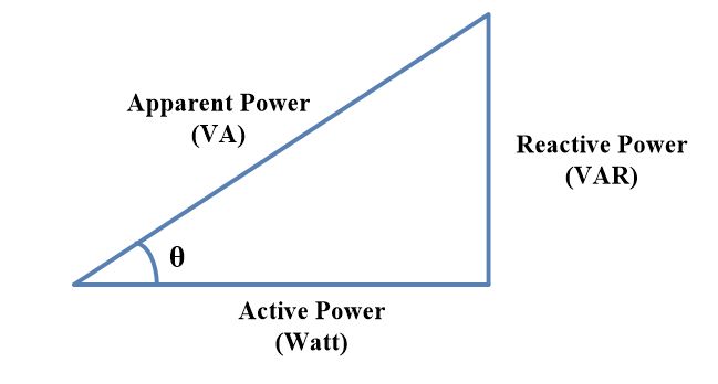
Where the real power P is along the horizontal axis, the reactive power Q is along the vertical axis, and the apparent power S is the hypotenuse.Then,
$Q=S*Sin\theta ~~~~~\text{ }\cdots \text{ }~~\left( 4 \right)$
And
$S=\sqrt{{{P}^{2}}+{{Q}^{2}}}$
Reactive Power
Reactive power Q is defined by equation (4)
$Q=VI~Sin\theta $
If a circuit has inductive element only, Q is inductive reactive Power, QL expressed in terms of VARS.
If the circuit has capacitive element only, Q is capacitive reactive power,QC expressed by the same unit as QL.
If the circuit contains both inductance and capacitance, the net reactive power,Qt is the difference between the capacitive reactive power and inductive reactive power. In such a case, capacitor returns energy to the circuit while inductor takes energy from the circuit.
- You May Also Read: What is Power Factor and How to Correct it?
Active and Reactive Power Key Takeaways
Understanding apparent, active, and reactive power is essential for efficient design, analysis, and operation of electrical power systems. These concepts play a vital role in optimizing energy usage, improving power factor, minimizing losses, and ensuring the reliability and stability of both industrial and residential electrical applications.
1 thought on “Apparent, Active and Reactive Power”