To define the composition of a four-terminal, two-port network, we need four parameters. The test circuit of Figure 1 gives a set of parameters called the open-circuit impedance parameters (z-parameters) of the network.
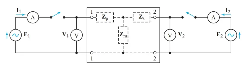
Figure 1 Determining open-circuit impedance parameters
We start by opening the right-hand switch in Figure 1 so that I2 = 0. Leaving this switch open prevents the output circuit from affecting the measurement of input impedance. When we close the left-hand switch, the readings from the voltmeter measuring V1 and the ammeter measuring I1 give us a V/I ratio that represents only the open-circuit input impedance of the network.
We now open the left-hand switch and close the right-hand switch. I1 becomes zero, making the voltage drop across Zp zero. However, there is a reading on the voltmeter measuring V1 as a part of I2 is coupled back to the input side of the network. The ratio between the voltage, V1, at the input terminals (port 1) and the current, I2, flowing into the output terminals (port 2) is an impedance (in ohms) that indicates the amount of output-to-input (reverse-transfer) coupling in the network.
The same technique also produces parameters for the output impedance and input-to-output coupling. Thus, there are four open-circuit impedance parameters:
Open-circuit input impedance:
\[\begin{matrix}{{\text{z}}_{\text{11}}}\text{=}\frac{{{\text{E}}_{\text{1}}}}{{{\text{I}}_{\text{1}}}}\left( with\text{ }{{\text{I}}_{\text{2}}}=0 \right) & {} & \left( 1 \right) \\\end{matrix}\]
Open-circuit reverse-transfer impedance:
\[\begin{matrix}{{\text{z}}_{\text{12}}}\text{=}\frac{{{\text{V}}_{\text{1}}}}{{{\text{I}}_{\text{2}}}}\left( with\text{ }{{\text{I}}_{\text{1}}}=0 \right)Open-Circuit & {} & \left( 2 \right) \\\end{matrix}\]
Open-circuit forward-transfer impedance:
\[\begin{matrix}{{\text{z}}_{21}}\text{=}\frac{{{\text{V}}_{\text{2}}}}{{{\text{I}}_{\text{1}}}}\left( with\text{ }{{\text{I}}_{\text{2}}}=0 \right)Open-Circuit & {} & \left( 3 \right) \\\end{matrix}\]
Open-circuit forward-transfer impedance:
\[\begin{matrix}{{\text{z}}_{\text{22}}}\text{=}\frac{{{\text{E}}_{\text{2}}}}{{{\text{I}}_{\text{2}}}}\left( with\text{ }{{\text{I}}_{\text{1}}}=0 \right) & {} & \left( 4 \right) \\\end{matrix}\]
Having determined the four z-parameters, we now close both switches in Figure 1 so that the network actually does couple the output and input circuits. Consequently, both z11 and z12 are now present in the input circuit, and V1 consists of two voltages in series: the IZ drop due to I1 flowing in z11, plus a coupled voltage representing I2 flowing through the reverse-transfer impedance z12.
Applying a Kirchhoff’s voltage-law equation to the input terminals (port 1) of the network gives
\[\begin{matrix}{{\text{z}}_{\text{11}}}{{\text{I}}_{\text{1}}}\text{+}{{\text{z}}_{\text{12}}}{{\text{I}}_{\text{2}}}\text{=}{{\text{E}}_{\text{1}}} & {} & \left( 5 \right) \\\end{matrix}\]
Similarly, for the output terminals (port 2),
\[\begin{matrix}{{\text{z}}_{\text{21}}}{{\text{I}}_{\text{1}}}\text{+}{{\text{z}}_{\text{22}}}{{\text{I}}_{\text{2}}}\text{=}{{\text{E}}_{2}} & {} & \left( 6 \right) \\\end{matrix}\]
The next step is to determine the equivalent circuit represented by these two Kirchhoff’s voltage-law equations. The sum of two voltages at the input terminals represents a series circuit.
With the left-hand switch open and the right-hand switch closed in Figure 1, we discovered a voltage, V1, across the input port due to the output current I2. Hence, we can argue that we are looking into a Thévenin-equivalent voltage source that is dependent on the current in some other part of the circuit. The open-circuit voltage of this current-controlled voltage source is z12I2, and z11 appears to be the internal impedance of the source.
Looking into the output terminals, we see a similar Thévenin-equivalent dependent voltage source. Hence, Figure 2 is the z-parameter equivalent circuit for the open-circuit impedance parameters of a four-terminal coupling network.
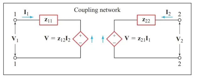
Figure 2 z-parameter equivalent circuit
We can now find the open-circuit impedance parameters for the T-network shown by dashed lines in Figure 1. With the left-hand switch closed and the right-hand switch open,
\[{{\text{I}}_{\text{1}}}\text{=}\frac{{{\text{E}}_{\text{1}}}}{{{\text{Z}}_{\text{p}}}\text{+}{{\text{Z}}_{\text{m}}}}\]
And
\[\begin{matrix}{{\text{Z}}_{\text{p}}}\text{+}{{\text{Z}}_{\text{m}}}\text{=}\frac{{{\text{E}}_{\text{1}}}}{{{\text{I}}_{\text{1}}}}\text{=}{{\text{z}}_{\text{11}}} & {} & \left( 7 \right) \\\end{matrix}\]
At the same time, the voltmeter measuring V2 reads
${{\text{V}}_{\text{2}}}\text{=}{{\text{Z}}_{\text{m}}}{{\text{I}}_{\text{1}}}$
Hence,
\[\begin{matrix}{{\text{Z}}_{\text{m}}}\text{=}\frac{{{\text{V}}_{\text{2}}}}{{{\text{I}}_{\text{1}}}}={{z}_{21}} & {} & \left( 8 \right) \\\end{matrix}\]
Similarly, with the left-hand switch in Figure 1 open and the right-hand switch closed,
\[\begin{matrix}{{\text{Z}}_{\text{s}}}\text{+}{{\text{Z}}_{\text{m}}}\text{=}\frac{{{\text{E}}_{\text{2}}}}{{{\text{I}}_{\text{2}}}}\text{=}{{\text{z}}_{22}} & {} & \left( 9 \right) \\\end{matrix}\]
And
\[\begin{matrix}{{\text{Z}}_{\text{m}}}\text{=}\frac{{{\text{V}}_{\text{1}}}}{{{\text{I}}_{\text{2}}}}\text{=}{{\text{z}}_{12}} & {} & \left( 10 \right) \\\end{matrix}\]
Rearranging Equations 7 to 10 gives the three T-network components in terms of the z-parameters:
\[\begin{align}& \begin{matrix}{{Z}_{m}}={{z}_{12}}={{z}_{21}} & {} & \left( 11 \right) \\\end{matrix} \\& \begin{matrix}{{Z}_{p}}={{z}_{11}}-{{z}_{12}} & {} & \left( 12 \right) \\\end{matrix} \\& \begin{matrix}{{Z}_{s}}={{z}_{22}}-{{z}_{21}} & {} & \left( 13 \right) \\\end{matrix} \\\end{align}\]
If we know the z-parameters for a passive coupling network, we can readily find the equivalent T-network, or vice versa. For a T-network, the forward-transfer and reverse-transfer impedances must be equal. This equality is characteristic of any passive network containing only resistance and reactance elements. Consequently, we call Zm the mutual impedance of the coupling network.
In active networks containing transistors, z12 and z21 must differ for amplification to take place. The z-parameter equivalent circuit of Figure 2 can represent both passive and active coupling networks.
Summary
• The open-circuit impedance parameters of a two-port network can be determined by representing the network by its equivalent T-network.