Resistance and impedance both represent opposition to electric current. However, resistance opposes both direct and alternating current, while the reactance component of impedance opposes only changing current. Calculations for DC circuits can be done with scalar quantities and ordinary algebra. But impedance is a phasor quantity in AC circuits, and so calculations for impedance networks are based on phasor algebra.
With phasor algebra, all the relationships for resistance networks also apply to impedance networks.
Impedances in Series
At any particular instant, the circuit relationships in Figure 1(a) are exactly the same as in a DC circuit that has the voltages and currents that prevail at that instant. Consequently, Kirchhoff’s voltage law gives
\[e={{v}_{T}}={{v}_{R}}+{{v}_{L}}\]
To extend Kirchhoff’s voltage law to the much more useful RMS values for AC circuit parameters, we must use phasor quantities. Then, the Kirchhoff’s voltage-law relationship for Figure 1(a) can be written as
${{\text{E}}_{\text{T}}}\text{=}{{\text{V}}_{\text{R}}}\text{+}{{\text{V}}_{\text{L}}}$
Each term in this equation is a phasor, and the addition must be done with phasor algebra.
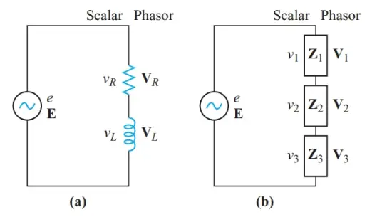
Figure 1 Kirchhoff’s voltage law applied to an AC circuit
We can apply the phasor form of Kirchhoff’s voltage law to the series circuit of Figure 1(b):
\[\begin{matrix}\text{E=}{{\text{V}}_{\text{T}}}\text{=}{{\text{V}}_{\text{1}}}\text{+}{{\text{V}}_{\text{2}}}\text{+}{{\text{V}}_{\text{3}}} & {} & \left( 1 \right) \\\end{matrix}\]
Dividing every term in Equation 1 by the common current in the series circuit gives
\[\frac{{{\text{V}}_{\text{T}}}}{\text{I}}\text{=}\frac{{{\text{V}}_{\text{1}}}}{\text{I}}\text{+}\frac{{{\text{V}}_{\text{2}}}}{\text{I}}\text{+}\frac{{{\text{V}}_{\text{3}}}}{\text{I}}\]
By definition, Z = V/I. Therefore,
$\begin{matrix}{{\text{Z}}_{\text{T}}}\text{=}{{\text{Z}}_{\text{1}}}\text{+}{{\text{Z}}_{\text{2}}}\text{+}{{\text{Z}}_{\text{3}}} & {} & \left( 2 \right) \\\end{matrix}$
The total impedance of impedances in series is their phasor sum. This relationship can be extended to any number of impedances in series:
Example 1
Find the total impedance when ${{Z}_{1}}=60\angle +{{60}^{o}}\Omega \text{ and }{{Z}_{2}}=80\angle -{{45}^{o}}\Omega $ are connected in series. Give the answer in polar form.
Solution
Step 1
Draw a circuit diagram and sketch an impedance diagram to indicate the approximate total impedance, as shown in Figure 2.
Step 2
Convert the impedances to rectangular form, and add the components:
\[\begin{align}& {{Z}_{1}}=60\cos {{60}^{o}}+j60\cos {{60}^{o}}=30+j52 \\& {{Z}_{2}}=80\cos {{45}^{o}}-j80\sin {{45}^{o}}=56.6-j56.62 \\& {{Z}_{T}}={{Z}_{1}}+{{Z}_{2}}=86.6-j4.6 \\\end{align}\]
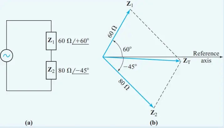
Figure 2 Impedances in series
Step 3
Convert the total impedance into polar form:
\[\begin{align}& \phi ={{\tan }^{-1}}\frac{-4.6}{86.6}=-{{3}^{o}} \\& Z=\frac{86.6}{\cos \left( -{{3}^{o}} \right)}=86.7\Omega \\& Z=87\angle -{{3}^{o}}\Omega \\\end{align}\]
Example 1a
Find the total impedance when ${{Z}_{1}}=10,000+j15,000\Omega \text{ , }{{Z}_{2}}=47,000+j0\Omega \text{ and }{{Z}_{3}}=25,000-j10,000\Omega $ are connected in series.
Solution
Simply add the rectangular coordinates.
\[\begin{align}& {{Z}_{1}}=10,000+j15,000 \\& {{Z}_{2}}=4700+j0 \\& {{Z}_{3}}=25,000-j10,000 \\& {{Z}_{T}}=39,700+j5000\Omega \\\end{align}\]
It may appear from the simple solution of Example 1a that impedance should always be expressed in rectangular coordinates. However, the rectangular coordinates of an impedance represent resistance and a reactance in series. Therefore, the addition process of Example 1a applies only to series impedances.
We can now extend the voltage-divider principle to series impedances. With phasor quantities, we can write the following expression:
\[\begin{matrix}{{V}_{n}}=E\frac{{{Z}_{n}}}{{{Z}_{T}}} & {} & \left( 3 \right) \\\end{matrix}\]
Example 2
Find the voltage drop across Z1 in the circuit of Figure 2(a) when the applied voltage is $120\angle {{0}^{o}}$.
Solution
Step 1
Use Ohm’s law with ZT as determined in Example 1:
\[\begin{align}& I=\frac{E}{{{Z}_{T}}}=\frac{120\angle {{0}^{o}}V}{86.7\angle -{{3}^{o}}\Omega }=1.38\angle +{{3}^{o}}A \\& {{V}_{1}}=I{{Z}_{1}}=1.38\angle +{{3}^{o}}\times 60\angle +{{60}^{o}}=83\angle +{{63}^{o}}V \\\end{align}\]
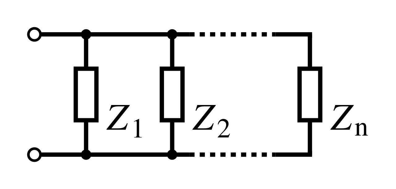
Impedances in Parallel
As with parallel DC circuits, we can analyze parallel AC circuits by considering the circuit’s ability to conduct current. Two sets of parameters are proportional to a circuit’s ability to pass current:
• The total of all branch currents
• The total of all branch admittances
For parallel branches in an AC circuit, Kirchhoff’s current law gives
\[\begin{matrix}{{\text{I}}_{\text{T}}}\text{=}{{\text{I}}_{\text{1}}}\text{+}{{\text{I}}_{\text{2}}}\text{+}{{\text{I}}_{\text{3}}}+\cdots & {} & \left( 4 \right) \\\end{matrix}\]
Dividing every term in Equation 4 by the common voltage across parallel branches gives
\[\frac{{{I}_{T}}}{V}=\frac{{{I}_{1}}}{V}+\frac{{{I}_{2}}}{V}+\frac{{{I}_{3}}}{V}+\cdots \]
Since admittance is defined as Y = 1/Z,
$\begin{matrix}{{Y}_{T}}={{Y}_{1}}+{{Y}_{2}}+{{Y}_{3}}+\cdots & {} & \left( 5 \right) \\\end{matrix}$
The total admittance of parallel branches is the phasor sum of the branch admittances.
The equivalent impedance of a parallel AC circuit can be determined in two ways: by the total-current method (from Equation 4),
\[\begin{matrix}{{\text{Z}}_{\text{eq}}}\text{=}\frac{\text{E}}{{{\text{I}}_{\text{T}}}} & {} & \left( 6 \right) \\\end{matrix}\]
And by the total-admittance method (from Equation 5)
\[\begin{matrix}{{\text{Z}}_{\text{eq}}}\text{=}\frac{1}{{{\text{Y}}_{\text{T}}}} & {} & \left( 7 \right) \\\end{matrix}\]
For the special case of two branches in parallel,
\[{{Y}_{T}}={{Y}_{1}}+{{Y}_{2}}=\frac{1}{{{Z}_{1}}}+\frac{1}{{{Z}_{2}}}=\frac{{{Z}_{2}}-{{Z}_{1}}}{{{Z}_{1}}{{Z}_{2}}}\]
Inverting this equation gives
\[\begin{matrix}{{Z}_{eq}}=\frac{{{Z}_{1}}{{Z}_{2}}}{{{Z}_{2}}+{{Z}_{1}}} & {} & \left( 8 \right) \\\end{matrix}\]
Example 3
Find the equivalent impedance for ${{Z}_{1}}=60\angle +{{60}^{o}}\Omega \text{ and }{{Z}_{2}}=80\angle -{{45}^{o}}\Omega $ connected in series.
Solution
Step 1
Draw a schematic diagram and a current phasor diagram, as in Figure 3.
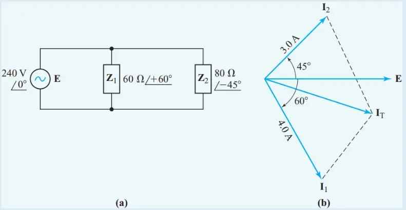
Figure 3 Total-current method for Example 3
Step 2
Assume a convenient value of applied voltage, such as E = 240 ∠ 0° V. Then determine the branch currents:
\[\begin{align}& {{\text{I}}_{\text{1}}}\text{=}\frac{\text{E}}{{{\text{Z}}_{\text{1}}}}=\frac{240\angle {{0}^{o}}V}{60\angle +{{60}^{o}}\Omega }=4.0\angle -{{60}^{o}}A \\& {{\text{I}}_{\text{2}}}\text{=}\frac{\text{E}}{{{\text{Z}}_{\text{2}}}}=\frac{240\angle {{0}^{o}}V}{80\angle -{{45}^{o}}\Omega }=3.0\angle +{{45}^{o}}A \\\end{align}\]
Step 3
Convert the branch currents to rectangular form and add the components:
\[\begin{align}& {{\text{I}}_{\text{1}}}=4\cos {{60}^{o}}-j60\sin {{60}^{o}}=2-j3.464 \\& {{\text{I}}_{\text{2}}}=3\cos {{45}^{o}}+j3\sin {{45}^{o}}=2.121+j52.121 \\& {{\text{I}}_{\text{T}}}\text{=}{{\text{I}}_{\text{1}}}\text{+}{{\text{I}}_{\text{2}}}=4.121-j1.343A \\\end{align}\]
Step 4
Convert the total current to polar form:
$\begin{align}& \phi ={{\tan }^{-1}}\frac{-1.343}{4.121}=-{{18}^{o}} \\& {{I}_{T}}=\frac{4.121}{\cos \left( -{{18}^{o}} \right)}=4.334A \\& {{I}_{T}}=4.334\angle -{{18}^{o}}A \\\end{align}$
Step 5
Use the total current to calculate the equivalent impedance:
\[{{Z}_{eq}}=\frac{E}{{{I}_{T}}}=\frac{240\angle {{0}^{o}}V}{4.334\angle -{{18}^{o}}A}=55\angle +{{18}^{o}}\]
Since the same voltage appears across parallel branches, we can establish the current-divider principle for AC circuits from the relationship:
\[\text{V =}{{\text{I}}_{\text{1}}}{{\text{Z}}_{\text{1}}}\text{=}{{\text{I}}_{\text{2}}}{{\text{Z}}_{\text{2}}}\]
\[\begin{matrix}\frac{{{I}_{1}}}{{{I}_{2}}}=\frac{{{Z}_{2}}}{{{Z}_{1}}} & {} & \left( 9 \right) \\\end{matrix}\]
Therefore, the ratio of the currents in any two parallel branches of an AC circuit is the inverse of the ratio of the impedances of the two branches. However, it is more convenient to express the current-divider principle in terms of branch admittances. Since,
\[\text{V=}\frac{{{\text{I}}_{\text{n}}}}{{{\text{Y}}_{\text{n}}}}\text{=}\frac{{{\text{I}}_{\text{T}}}}{{{\text{Y}}_{\text{T}}}}\]
\[\begin{matrix}{{I}_{n}}={{I}_{T}}\frac{{{Y}_{n}}}{{{Y}_{T}}} & {} & \left( 10 \right) \\\end{matrix}\]
As with DC circuits, the current-divider equation 10 is the dual of the voltage-divider equation 3. When there are only two parallel branches, we can use Equation 8 to substitute for 1/YT in Equation 10:
\[\begin{matrix}{{I}_{1}}={{I}_{T}}\frac{{{Z}_{2}}}{{{Z}_{1}}+{{Z}_{2}}} & {} & \left( 11 \right) \\\end{matrix}\]
Example 4
What current does a 10∠-45°kΩ load draw from the Norton-equivalent source shown in Figure 4?
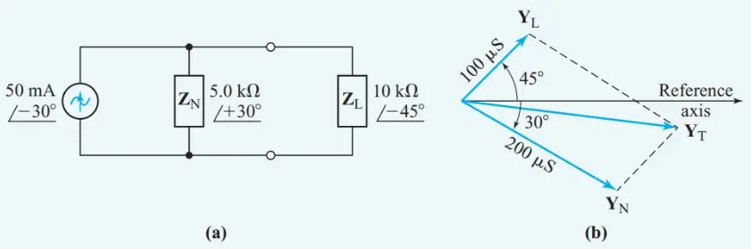
Figure 4 Diagrams for Example 4
Using the current-divider principle
Step 1
$\begin{align}& {{Y}_{L}}=\frac{1}{{{Z}_{L}}}=\frac{1}{10\angle -{{45}^{o}}k\Omega }=100\angle +{{45}^{o}}\mu S=70.71+j70.71\mu S \\& {{Y}_{N}}=\frac{1}{{{Z}_{N}}}=\frac{1}{5\angle +{{30}^{o}}k\Omega }=200\angle -{{30}^{o}}\mu S=173.2-j100\mu S \\& {{Y}_{T}}=243.91-j29.29\mu S=245.7\angle -{{6.85}^{o}}\mu S \\\end{align}$
Step 2
From Equation 10,
\[{{\text{I}}_{\text{L}}}\text{=}{{\text{I}}_{\text{T}}}\frac{{{\text{Y}}_{\text{L}}}}{{{\text{Y}}_{\text{T}}}}=50\angle -{{30}^{o}}mA\times \frac{100\angle +{{45}^{o}}\mu S}{245.7\angle -{{6.85}^{o}}\mu S}=20\angle +{{22}^{o}}mA\]
Summary
• The total impedance of impedances in series is their phasor sum.
• The total admittance of admittances in parallel is their phasor sum.