The article discusses various methods for controlling the speed of DC motors, including field current control, armature voltage control, and armature resistance control. It explains how these techniques affect torque, speed, and power, and compares their applications in both shunt and series DC motors.
The major advantage of DC motors has been the ability to control the speed-torque characteristic over a fairly wide range of speeds for a given torque. Variable-speed AC drives now make it possible to use induction motors to perform tasks that previously could only be done by DC motors. However, there are many DC motors still being used in industry for variable-speed applications.
From the speed equation (equation 1) for the shunt DC motor, we can observe that there are two controllable variables that could be used to change the speed of the machine.
\[\begin{matrix} n=\frac{{{V}_{t}}-{{I}_{a}}{{R}_{a}}}{{{K}_{g}}{{\phi }_{p}}} & {} & \left( 1 \right) \\\end{matrix}\]
In particular, decreasing the flux in the denominator would allow the speed to increase. That can be done easily by increasing the field rheostat resistance.The other controllable variable is the terminal voltage of the machine. By decreasing the terminal voltage, the speed would drop.One other possibility is to change the resistance in the armature circuit.
All three of these techniques will be described below.
Field Current Control
Field current control is the most common method of controlling the speed of a DC shunt or compound motor. Field current control allows the speed to be increased above some base value that is determined by the terminal voltage of the motor.
This method is simple, inexpensive, and doesn’t cause much change in the motor losses. The lowest speed attainable for a DC shunt motor at a given terminal voltage occurs when the field rheostat is adjusted to zero.
Adding resistance by adjusting the rheostat causes lower field current and flux. If the flux per pole decreases, the denominator of equation 1 decreases and the speed of the machine increases.
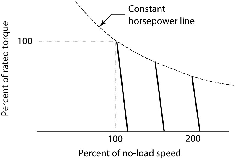
Figure 1: Control of DC shunt motor speed by shunt field rheostat.
Figure 1 shows the motor torque versus speed for a shunt DC motor with several values of field resistance. The relationship of equation 2 is linear between motor speed and torque, so the speed drops linearly as the torque increases.
\[\begin{matrix} n=\frac{{{V}_{t}}-{{R}_{a}}\left( \frac{{{T}_{d}}}{{{K}_{m}}{{\phi }_{p}}} \right)}{{{K}_{g}}{{\phi }_{p}}} & {} & \left( 2 \right) \\\end{matrix}\]
The speed of the machine when rated voltage is applied and rated torque is delivered is called the base speed of the machine.
By increasing the field rheostat resistance, we move to a new torque-speed line that provides an operating speed above the base speed of the motor. Figure 1 shows two other such lines.
It is important, however, to note that the machine is rated in terms of how much power it can deliver. Thus, we must ensure that we don’t overload the machine. As we know that the power delivered by a motor is proportionate to its speed times the torque it delivers. In SI units,
$\begin{matrix} P=\omega T & {} & \left( 3 \right) \\\end{matrix}$
Where ω is the radian rotational speed of the motor and T is the torque delivered to the shaft.
From equation 3, it is clear that an increase in speed will require a corresponding decrease in torque to keep the power constant. This means that the rated torque of a motor must decrease as the operating speed is decreased. The dashed line in Figure 1 shows how the torque must decrease to keep the horsepower constant.
The field rheostat method of speed control yields a so-called constant horse power drive, meaning the rated horsepower is constant. Of course, the actual horsepower that is delivered depends on the load.
Speed ranges of 8 to 1 are possible for small motors, 4 to 1 for medium motors, and 2 to 1 for large motors. Since field rheostat control only allows us to increase the speed of the motor, we must use another method to decrease the speed of the motor.
Armature Voltage Control
From equation 1, decreasing the terminal voltage will decrease the speed of the motor, assuming the flux per pole of the field remains unchanged.
Figure 2 shows the effect of reducing the voltage applied to the machine. In the steady state, a reduction in the terminal voltage is accompanied by almost an equal reduction in the C-EMF.
If the flux is maintained constant (by separately exciting the field or by rheostat adjustment), then the motor speed varies directly with the voltage.
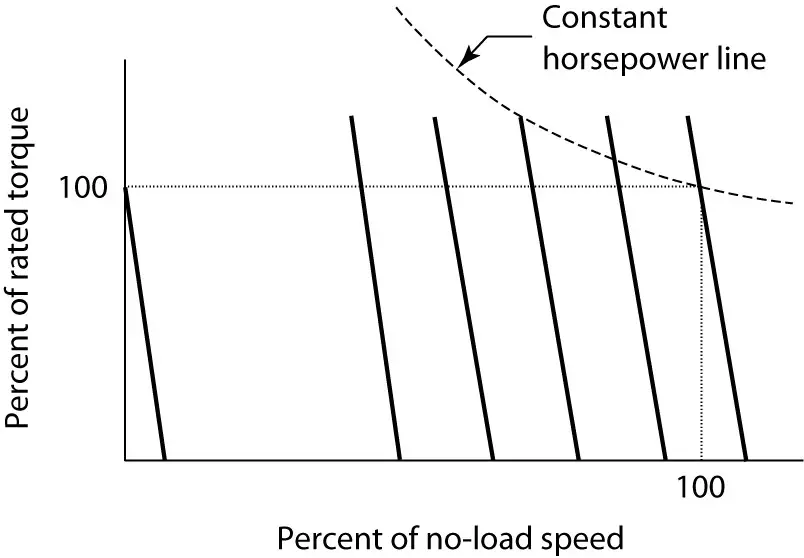
Figure 2: Armature voltage control of a DC motor.
As the speed is reduced below the base speed, the torque can remain at 100% of rated value, but the power will be de-rated because ω is getting smaller.
Recall that ${{T}_{d}}={{K}_{m}}{{\phi }_{p}}{{I}_{a}}$and the maximum values of flux and armature current are essentially fixed by the iron and copper in the motor.
Figure 2 also shows a constant horsepower line, which clearly requires more than rated torque as the speed drops. Thus, the horsepower rating of the motor must drop as the speed decreases.
This method of speed control yields a so-called constant torque drive, meaning the motor can deliver rated torque. In fact, it is possible for a DC motor to deliver rated torque at zero speed, thus producing a holding torque.
The combination of field rheostat and armature voltage control can produce a drive with a very wide range of operating speeds.
Figure 3 shows the rated torque and horsepower for such a drive. Below base speed, the drive is rated for constant torque and variable horsepower, while above-rated speed, it is rated for constant horsepower and variable torque.
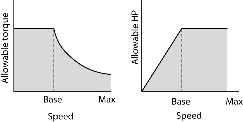
Figure 3: Torque and horsepower ratings for a DC motor above and below base speed.
Armature Resistance Control
Looking again at the speed equation (equation 1), increasing the armature circuit resistance would decrease the speed of the motor, assuming the terminal voltage and field flux remain the same. Figure 4 shows how this could be accomplished by placing a variable resistance in series with the armature.
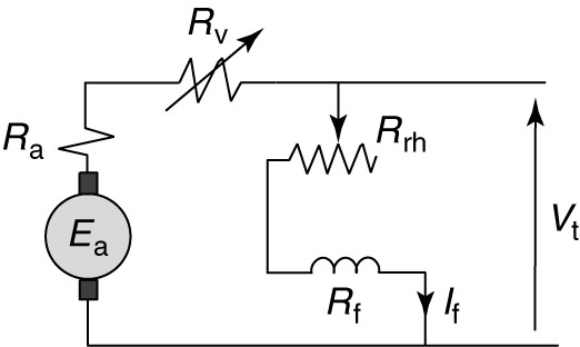
Figure 4: Equivalent circuit of a shunt DC motor with armature resistance control.
It is important that the extra resistance be placed in the circuit between the armature and the shunt field, as shown, to avoid affecting the field flux.
Figure 5 shows how the motor speed changes when resistance is added to the armature circuit. Adding armature circuit resistance has the effect of changing the slope of the torque-speed characteristic, as shown in Figure 5.
Although this method is relatively easy to implement, it adds extra losses to the system be cause resistance dissipates energy all of the time it is in the circuit.
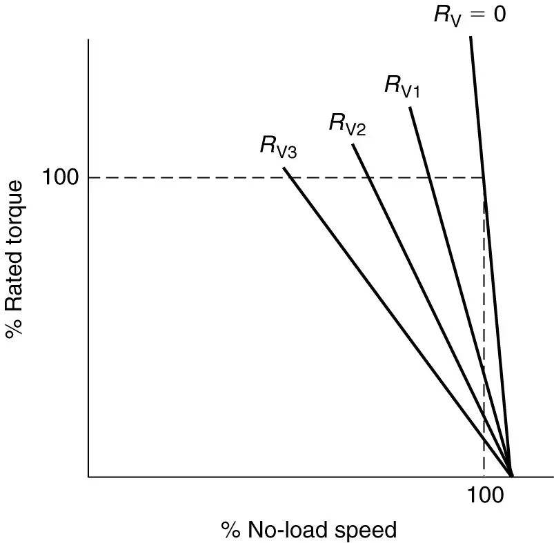
Figure 5: Speed variation of a shunt DC motor due to armature control.
Series Motor Speed Control
The speed of a series DC motor can also be controlled using either armature voltage control or armature circuit resistance.
As with the shunt motor, resistance control is cheap but inefficient. Voltage control, on the other hand, is efficient but more expensive. Both produce essentially the same result as shown in Figure 6.
Adding armature resistance or decreasing the terminal voltage allows the motor to produce rated torque at a slower speed or less torque at rated speed, as shown by the dotted and dashed curves.
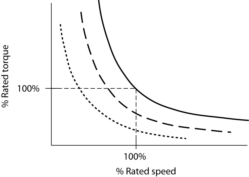
Figure 6: Speed control of a series DC motor.
Speed Control Methods of DC Motor Key Takeaways
Understanding the various methods of DC motor speed control—field current control, armature voltage control, and armature resistance control—is crucial for selecting the right approach in real-world applications. Each technique provides specific advantages that suit different operational requirements: field current control enables constant horsepower drives for high-speed operations, armature voltage control offers constant torque at lower speeds, and armature resistance control, though less efficient, is cost-effective for simple speed reductions. These methods are especially important in industries where precision speed regulation, torque control, and power efficiency are essential—such as in elevators, conveyors, electric vehicles, and robotics.