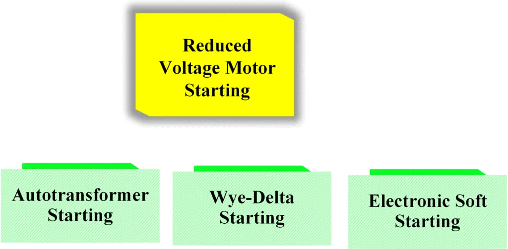
The article discusses various methods of reduced voltage motor starting used to limit inrush current in induction motors, including autotransformer starting, wye-delta starting, and electronic soft starting. It outlines the principles, control circuits, and operational differences among these techniques.
Induction motors draw very large currents when started at full voltage. Thus, it is desirable, especially for large motors, to start them at reduced voltage to keep the starting current low. Reduced voltage motor starting methods include resistance starting, reactance starting, autotransformer starting, wye-delta starting, part-winding starting, and electronic soft starting. Autotransformer, wye-delta, and electronic soft starting will be discussed in this section.
Autotransformer Starting
This method employs autotransformers in the lines between the source and the motor to reduce the motor starting voltage and thus the inrush current.
Taps are provided that allow the user to select 50%, 65%, or 80% of the line voltage. This reduces the starting current to a similar percentage of the full-voltage starting current.
It should be remembered that motor torque varies with the square of the voltage. Therefore, for the voltage settings listed above, the starting torque will be reduced to 25%, 42%, and 64% of rated starting torque, respectively.
Figure 1(a) illustrates the concept of autotransformer starting using three single-phase auto transformers connected in a wye configuration.
It is also possible to use only two autotransformers by connecting them in an open-delta. Figure 1(b) shows the method of two single-phase autotransformers connected in open-delta.
In either case, the motor is started with reduced voltage from the autotransformer and then is shifted to full voltage to run. To accomplish the transition from reduced voltage to full voltage requires a control circuit.
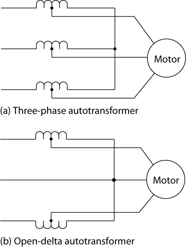
Figure 1: Autotransformer starting of an induction motor.
Autotransformer starting may be either open-transition or closed-transition.
In closed-transition starting, the motor is never removed from the supply during the starting period. In open-transition starting, the motor may be temporarily disconnected when moving from one incremental voltage to another, which can cause current surges. Closed-transition starting is a better method but costs more. Figure 2 illustrates closed-transition starting.
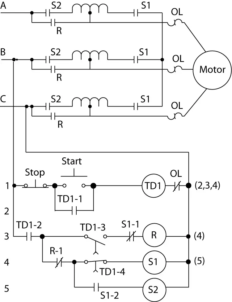
Figure 2: Closed-transition autotransformer starting.
The control circuit consists of time-delay relay TD1, two start contactors SI and S2, and one run contactor R. Pressing the start push button will result in the following sequence of events:
- Time-delay relay TD1 is energized, closing the instantaneous contacts TD1-1 and TD1-2. TD1-1 seals the start switch, and TD1-2 enables the lower portion of the ladder diagram.
- Because contacts R and TD1-4 are normally closed, contactor SI is energized.
- Contact Sl-1 closes to energize contactor S2.
- All SI and S2 contacts in the power circuit close, which connects the three autotransformers into a wye. The motor is connected to the mid point tap on the autotransformer, so the motor starts at reduced voltage.
- After a preset time delay, TD1-3 closes and TD1-4 opens. Contactors SI and S2 are de energized, removing the autotransformers from the circuit, and contactor R is energized, which applies full voltage to the motor.
Wye-Delta Starting
We know that three impedances connected in Wye receive a lower phase voltage than if they are connected in delta. That is the principle behind wye-delta starting.
Figure 3 illustrates the method of wye-delta starting. The motor windings are first connected in a wye configuration to start the motor. As a result, only 58% of the line voltage is applied to each phase of the motor.
After a preset time delay, the motor windings are reconnected in a delta configuration so that full line voltage is applied to the motor windings. The motors used for wye-delta starting are wound with 6 or 12 leads at the motor terminal box so the motor phase leads can be connected in either wye or delta.
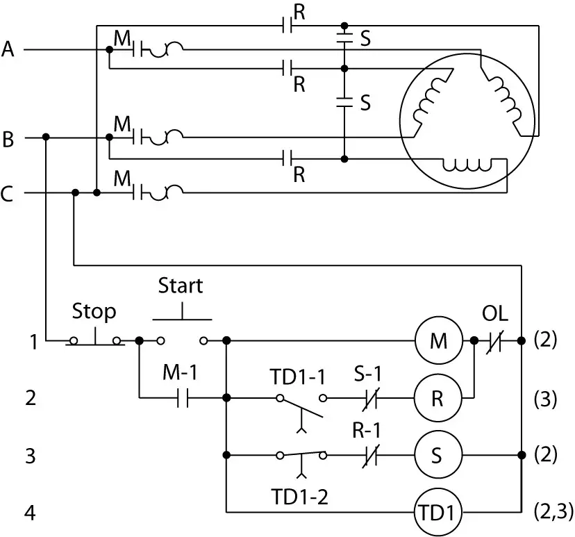
Figure 3: Wye-delta starting.
The wye-delta starter is inherently open-transition. Using a wye-delta starter reduces the starting current to about one-third of the full-voltage, locked-rotor current but also limits the starting torque to one-third of the normal locked-rotor torque.
The control circuit of Figure 3 consists of time-delay relay TD1, main contactor M, start contactor S, and run contactor R. Pressing the start push button will result in the following sequence of events:
- Contactor M is energized. Contact Ml closes to seal the start switch and enable the lower portion of the ladder diagram.
- Time-delay relay TD1 is energized. Since contacts TD1-2 and R1 are normally closed, contactor S is energized. Contactor R is not energized since the NC relay SI and NO relay TD1 are both open.
- All of the M and S contacts in the power circuit close to starting the motor in a wye configuration.
The M contacts connect the power source to the motor. The S contacts connect all three motor windings together at the center of the wye.
- After a preset time delay, contact TD1-1 closes and contact TD1-2 opens. Contactor S is de energized, and contactor R is energized.
- In the power circuit, contacts S open, undoing the wye connection, and contacts R close, connecting the motor windings in a delta configuration.
Electronic Soft Starting
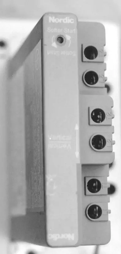
Commercially available, adjustable voltage systems use phase-controlled Thyristors or silicon- controlled rectifiers (SCRs). By controlling all three phases of the motor, we can start the motor with reduced voltage and ramp up to full voltage. Figure 4 shows a soft starter on the left and an electronic motor starter on the right.
 |
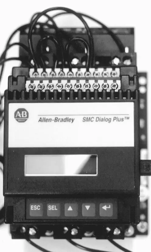 |
Figure 4: Soft starter and electronic motor starter.
Both are capable of providing a reduced-voltage start to the motor; however, the electronic motor starter does not need a conventional motor starter to operate but the soft starter does. Figure 5 shows, conceptually, an electronic soft starter.
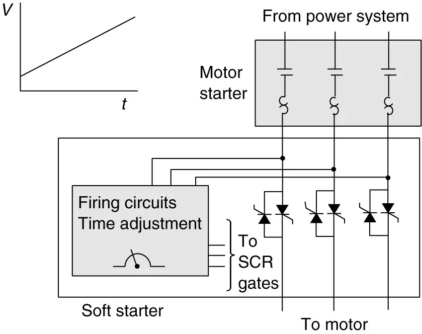
Figure 5: Electronic soft-starter concept.
Figures 6 and 7 illustrate the effect of the electronic soft starter on various motor characteristics. By using the electronic soft starter, the motor starting current, in this illustration, is limited to less than half the rated starting current, and the motor voltage is slowly ramped up to rated voltage.
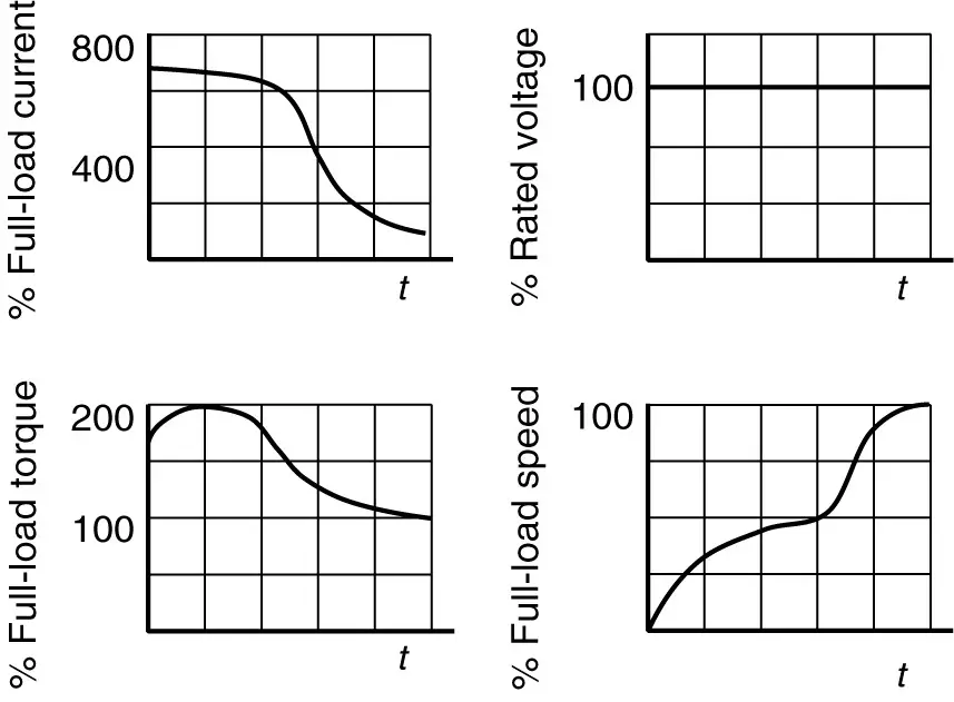
Figure 6: Motor characteristics with the hard start.
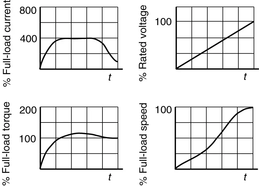
Figure 7: Motor characteristics with soft start.
Thus, the term soft start. The effect on torque and speed are also shown. Simple soft starters generally have an adjustable setting to control the speed at which the voltage is ramped up and the motor starts.
Electronic motor starters may offer relatively elaborate programming capabilities to adjust not only the time of acceleration but also the shape of the voltage ramp. They also offer communication capabilities to connect to PCs and PLCs.
Reduced Voltage Motor Starters Key Takeaways
In industrial and commercial applications, reduced voltage motor starting methods—such as autotransformer starting, wye-delta starting, and electronic soft starters—play a vital role in protecting electrical systems and equipment. These techniques are essential because they significantly limit the inrush current that occurs when induction motors start, thereby preventing voltage dips, reducing mechanical stress on the motor and connected equipment, and enhancing overall system reliability. By carefully controlling the starting torque and current, these methods ensure smoother motor startups, which is especially important in sensitive or high-power installations. Furthermore, advanced soft starters with programmable features and communication capabilities allow for integration with modern automation systems, making them highly suitable for a wide range of industrial applications.