The Boolean algebra is a set of specific rules that governs the mathematical relationships corresponding to the logic gates and their combinations. Their application is limited to two-valued (0 and 1) entries such as the inputs and outputs of logic gates.
Dealing with one single gate and a pair of inputs is a trivial task. When there are many parameters that are combined together through gates of various types, rules of Boolean algebra help to simplify and analyze the problem. Boolean algebra was developed by George Boole in 1854.
Laws of Boolean algebra
There are a number of laws for Boolean algebra. Here we study 10 of these laws considered to be more important, together with some examples for them. These laws govern the relationships that exist between two or more inputs to logic gates. They can be used to simplify circuits.
First Law
Any entity OR’ed with itself is equal to itself:
\[\text{A+A=A}\]
Example
\[\begin{align}& \text{1+1=1} \\& \text{0+0=0} \\\end{align}\]
Second law
Any entity AND’ed with itself is equal to itself:
\[A.A=A\]
Example
$\begin{align}& 1\times 1=1 \\& 0\times 0=0 \\\end{align}$
Third Law
OR and AND are commutative (the order does not matter):
$\begin{align}& A+B=B+A \\& A.B=B.A \\\end{align}$
Fourth Law
OR and AND are associative (the meaning is clear from the mathematical expression):
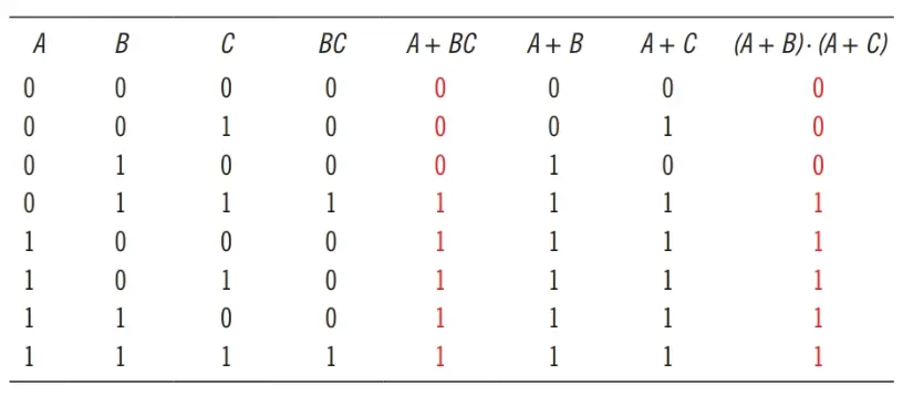
$\begin{align}& A.\left( B+C \right)=A.B+A.C \\& A+\left( B.C \right)=\left( A+B \right).\left( A+C \right) \\\end{align}$
This law is very important and useful, though can be confusing. The first one of these relationships follows the rules of algebra, but because the second one is not so clear the following truth table verifies its validity for various values of the three inputs. Compare the fifth and last columns.
Fifth Law
The result of any entity OR’ed with its own complement is 1:
$A+\overline{A}=1$
Example
$\begin{align}& 1+\overline{1}=1+0=1 \\& 0+\overline{0}=0+1=1 \\\end{align}$
Sixth Law
Anything AND’ed with its own complement is 0:
$A.\overline{A}=0$
Example
$\begin{align}& 1\times \overline{1}=1\times 0=0 \\& 0\times \overline{0}=0\times 1=0 \\\end{align}$
Seventh Law
Anything OR’ed with 0 is equal to itself; anything AND’ed with 0 equals 0:
\[\begin{align}& \begin{matrix}A+0=A & {} & \text{A can be 0 or 1} \\\end{matrix} \\& A\times 0=0 \\\end{align}\]
Eighth Law
Anything OR’ed with 1 is equal to 1; anything AND’ed with 1 is equal to itself.
$\begin{align}& A+1=1 \\& A\times 1=A \\\end{align}$
Example
$\begin{matrix}0+1=1 & 0\times 1=0 \\1+1=1 & 1\times 1=1 \\\end{matrix}$
The following two laws are called De Morgan laws:
Ninth Law (De Morgan First Law)
The inverse of the result of OR’ing two entities A and B is the same as if the inverse of those entities are AND’ed.
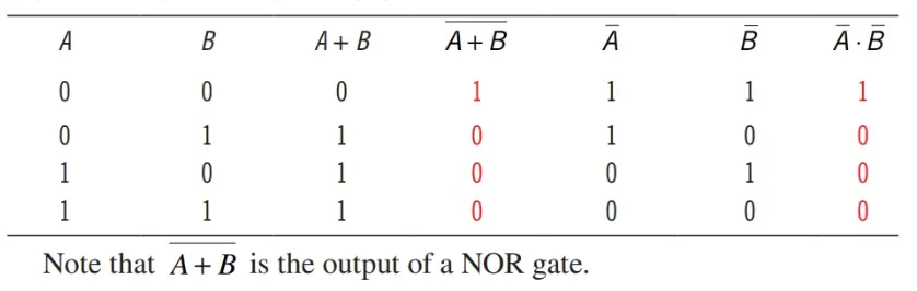
$\overline{A+B}=\overline{A}.\overline{B}$
Example
Because there are four different cases for two inputs all are shown in a truth table.
Truth Table for The first De Morgan law
Tenth Law (De Morgan Second Law)
The inverse of the result of AND’ing two entities A and B is the same as if the inverse of those entities are OR’ed.
$\overline{A\times B}=\overline{A}+\overline{B}$
Example
The following truth table illustrates the four possibilities.
Truth Table for The second De Morgan law
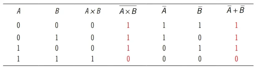
The term $\overline{A\times B}$ represents the output of a NAND circuit.
The implementation of De Morgan laws is converting AND and OR gates and vice versa when they are combined with a NOT gate. Consider the equivalence between the two expressions $\overline{A+B}$ and $\overline{A.B}$ between $\overline{A\times B}$ and $\overline{A}+\overline{B}$ based on De Morgan’s laws. The associated gates combinations are shown in Figure 1a. Note that an alternative way when a NOT gate is involved to invert an input signal is shown in Figure 1b.
Application of Boolean algebra Laws
Boolean algebra is employed to simplify logic circuits. Simplification often leads to having fewer components. Moreover, many cases can be found where two logic circuits lead to the same results. The two circuits, in this case, are equivalent to each other. Boolean algebra can help to verify and identify these circuits. This helps to reduce the number of gates in a circuit or synthesize a logic gate by some other gates, when necessary.
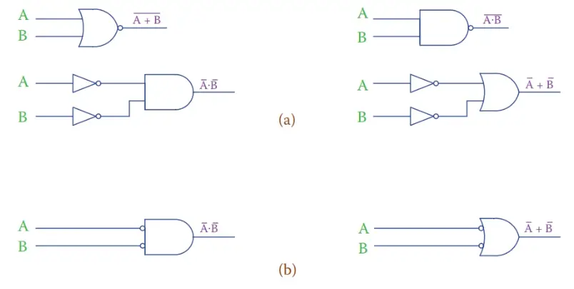
Figure 1 (a) Showing the first and second De Morgan law equivalent circuits. (b) Another way to show inputs to AND and OR gates if complements of signals A and B are the entries.
Sum of Products and Product of Sums
It is always possible to write the Boolean expression for an application based on a truth table. Suppose that for a process application there are three inputs that determine what action must be taken. For example, in a small office, it is expected that during the working hours the door is unlocked and some people are in the office. For this example the three parameters and their associated binary states are
\[\begin{matrix}\text{1}\text{. Office time (denoted by A):} & {} & \text{outside office time A = 0, inside office time A = 1;} \\\text{ 2}\text{. Door (denoted by B):} & {} & \text{door opened B = 0, door locked B = 1;} \\\text{ 3}\text{. Workers (denoted by C):} & {} & \text{no worker in C = 0, some workers present C = 1}\text{.} \\\end{matrix}\]
The condition is monitored by a security system, and in three cases an alarm sounds and notifies the security personnel: (1) when outside the office hours nobody is in the building and the door is opened, (2) when outside the office hours the door is locked, but some motion is sensed in the office, and (3) when inside the office hours, the door is open, but nobody is in the office.
You have noticed so far the pattern to represent three conditions, as seen in the previous truth tables with three inputs A, B, and C. The leftmost column starts with 0’s and for all other combinations of the other inputs has repeated 0’s, followed by the same number of 1’s. To the right of that, the other parameters are shown each one with repeated 0’s and 1’s covering all the possible variations of the parameters to its right.
Similar patterns can be formed for four, five, and more parameters. In the following truth table, the three sensitive cases for the alarm to sound are identified by asterisks.
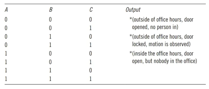
From this table, we want to write the logic expression for the scenario.
Note that for each case that the alarm must sound three conditions must simultaneously exist. This calls for AND’ing the three outputs corresponding to the cases. In this respect the expressions of the three cases are, respectively, $\overline{A}.\overline{B}.\overline{C}$ (all inputs have 0 values),$\overline{A}.B.C$ and $A.\overline{B}.\overline{C}$. Because each of these combinations must trigger the alarm, they must be OR’ed together. The expression for the output, therefore, is defined by
$\overline{A}.\overline{B}.\overline{C}+\overline{A}.B.C+A.\overline{B}.\overline{C}$
We are going to see the associated circuit for the above logic expression without simplification. The purpose is to show the way more involved circuits are presented.
In Figure 2 each parameter is shown with two vertical lines, one for its 1 value and one for its complement value through a NOT gate. Then, all connections for gates are drawn with horizontal lines while the points of connection are denoted by a black dot (there is no connection point between vertical and horizontal lines if there is no dot).
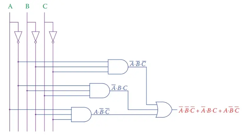
Figure 2 Method for representing inputs to complex circuits.
The representation of the circuit for the preceding problem is in the form of three AND gates driving an OR gate. This representation is often called the sum of products because the final expression is in the form of a number of multiplication products adding together.
In the same way that sum of products consists of a number of AND gates driving an OR gate, it is possible to have a number of OR gates driving an AND gate. Such a representation is called the product of sums because the final output function consists of a multiplication of a number of components each of which is the sum of some parameters.
De Morgan laws are the key to convert from multiplication to sum and vice versa. We have already seen examples of employing these laws for two parameters. For the current subject, first, we see the expansion for more parameters.
Considering the product A·B·C to be written as A· (B·C), by De Morgan law
$\overline{A.B.C}=\overline{A.\left( B.C \right)}=\overline{A}+\overline{B.C}=\overline{A}+\overline{B}+\overline{C}$
Similarly,
$\overline{A+B+C}=\overline{\left( A+B \right)+C}=\overline{A+B}.\overline{C}=\overline{A}.\overline{B}.\overline{C}$
The sum of products in question is
$Z=\overline{A}.\overline{B}.\overline{C}+\overline{A}.B.C+A.\overline{B}.\overline{C}$
It has three components that add together. But,
$\begin{matrix}\overline{A}.\overline{B}.\overline{C}=\overline{A+B+C,} & \overline{A}.B.C=\overline{A+\overline{B}+\overline{C},} & and & A.\overline{B}.\overline{C}=\overline{\overline{A}+B+C} \\\end{matrix}$
Because
\[\begin{align}& Z=\overline{\overline{A+B+C}+\overline{A+\overline{B}+\overline{C}}+\overline{\overline{A}+B+C}} \\& =\left( \overline{\overline{A+B+C}} \right).\left( \overline{\overline{A+\overline{B}+\overline{C}}} \right).\left( \overline{\overline{\overline{A}+B+C}} \right) \\& =\left( A+B+C \right).\left( A+\overline{B}+\overline{C} \right).\left( \overline{A}+B+C \right) \\\end{align}\]
Remember that,
$\overline{\overline{x}}=x$
Therefore,
\[Z=\overline{\left( A+B+C \right).\left( A+\overline{B}+\overline{C} \right).\left( \overline{A}+B+C \right)}\]
Which is in the form of the product of sums; however, the result must be inversed by a NOT gate. The corresponding circuit is depicted in Figure 3.
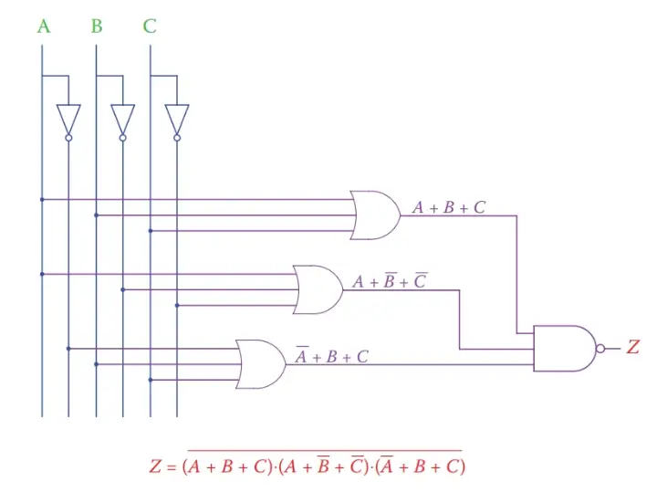
Figure 3 Alternative circuit for that in Figure 2.
Boolean Algebra Laws Key Takeaways
The laws of Boolean algebra play a fundamental role in the design, analysis, and simplification of digital logic circuits. These principles allow engineers and system designers to break down complex logic problems into manageable components, reducing circuit complexity and optimizing hardware performance. Through techniques like Sum of Products (SOP), Product of Sums (POS), and De Morgan’s Theorems, Boolean expressions can be systematically simplified to achieve the same functionality using fewer gates. This leads to cost-effective and efficient designs in real-world applications such as digital systems, embedded devices, security systems, and automated control units.